
Cylinder head for an internal combustion engine

Active Publication Date: 2018-02-13
AVL LIST GMBH
View PDF10 Cites 0 Cited by
  • Summary
  • Abstract
  • Description
  • Claims
  • Application Information

AI Technical Summary

Benefits of technology

The invention relates to a cooling system for valves, especially valves in combustion engines. The technical effects include an improved cooling system that reduces wear and increased efficiency, and a new design that optimizes heat dissipation from thermally highly loaded regions. The system includes at least one inwardly opening inlet that allows for an asymmetric flow of coolant, with one inlet positioned diametrically opposite the outlet. The design also includes a unique arrangement of at least two inlet ducts that intersect in a point on the valve seat ring or in the region of a cooling jacket, which further enhances cooling performance. Additionally, the system includes substantially sickle-shaped indentations in the region of the inlet and outlet to prevent flow losses and improve heat dissipation.

Problems solved by technology

These regions are at risk especially concerning thermal deformation and thus increased wear and tear to the valves.
These symmetrical cooling measures are inadequate however for avoiding thermal deformation of the exhaust valve bridges in the high-performance engines.
Although this cooling ring arrangement allows asymmetrical cooling of the valve seat rings, the dissipation of heat is insufficient due to the low flow quantities.
It is also disadvantageous that the separating region between the inlet and the outlet forms a non-cooled thermal bridge, and local overheating and thermal tensions can thus occur, especially when the separating region is positioned close to the thermally highly loaded web between the two exhaust valves.

Method used


Image

  • Cylinder head for an internal combustion engine
  • Cylinder head for an internal combustion engine
  • Cylinder head for an internal combustion engine

Examples


first embodiment

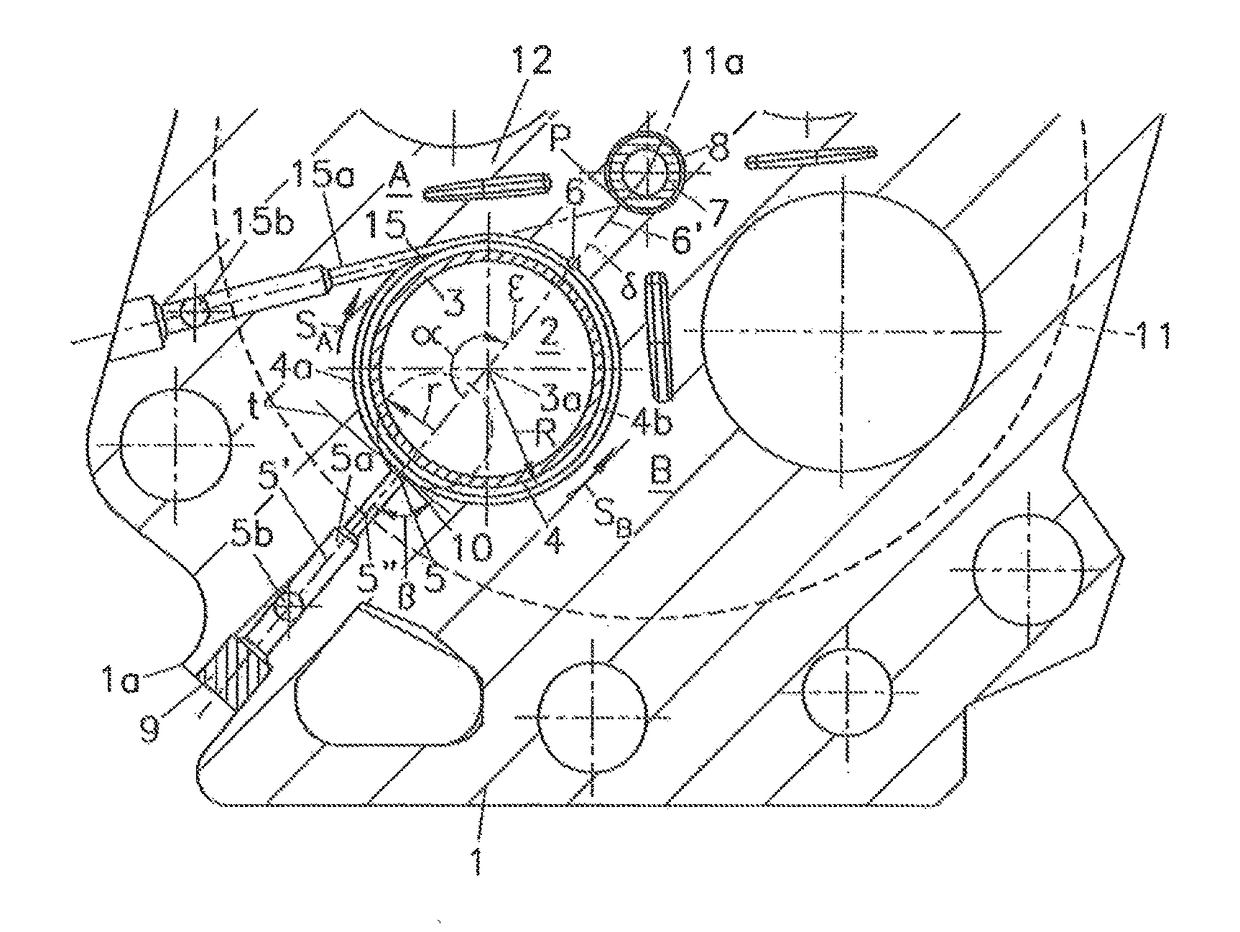
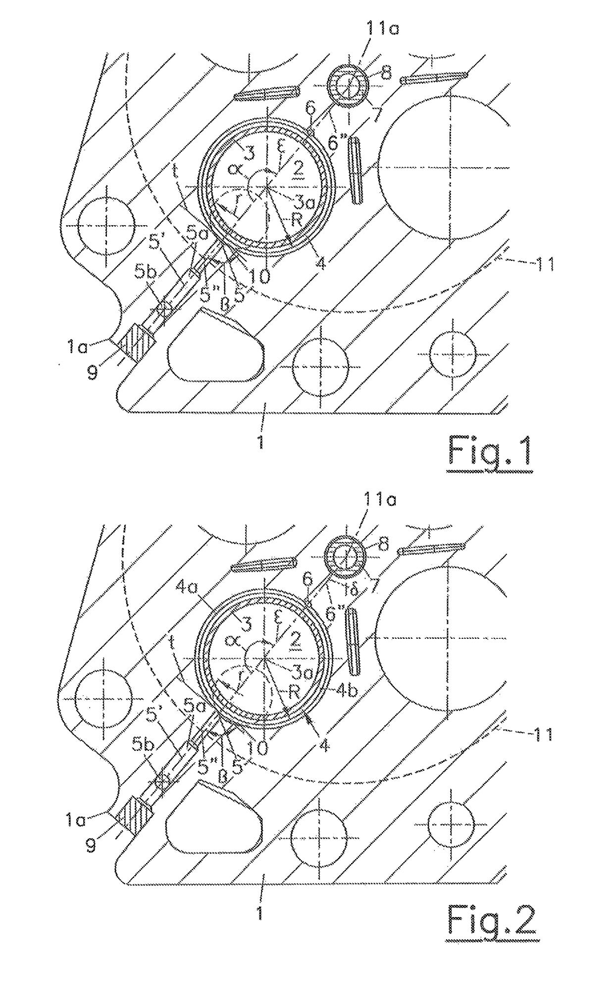
[0035]FIG. 1 shows a cylinder head 1, wherein the cooling duct 4 comprises a substantially sickle-shaped indentation 10 in the orifice region of the inlet duct 5a into the cooling duct 4, i.e., in the region of the inlet 5. The indentation 10 can substantially have the shape of a circular segment and can be produced by a cutting turning tool such as a milling cutter for example, Non-cutting production can also be considered, e.g., by an electric discharge machining method. The radius r of the indentation is advantageously selected from the range 0.2·R≦r≦0.8·R, wherein preferably the radius r of the indentation 10 lies between preferably 0.4·R and 0.6·R. As a result of an indentation 10 formed in this manner, flow losses in the region of the inlet 5 can be reduced substantially. A similar indentation can also be provided in an analogous manner in the region of the outlet 6 (not shown in greater detail). In FIG. 1, the indentation 10 is symmetrically arranged in relation to a plane E ...

second embodiment

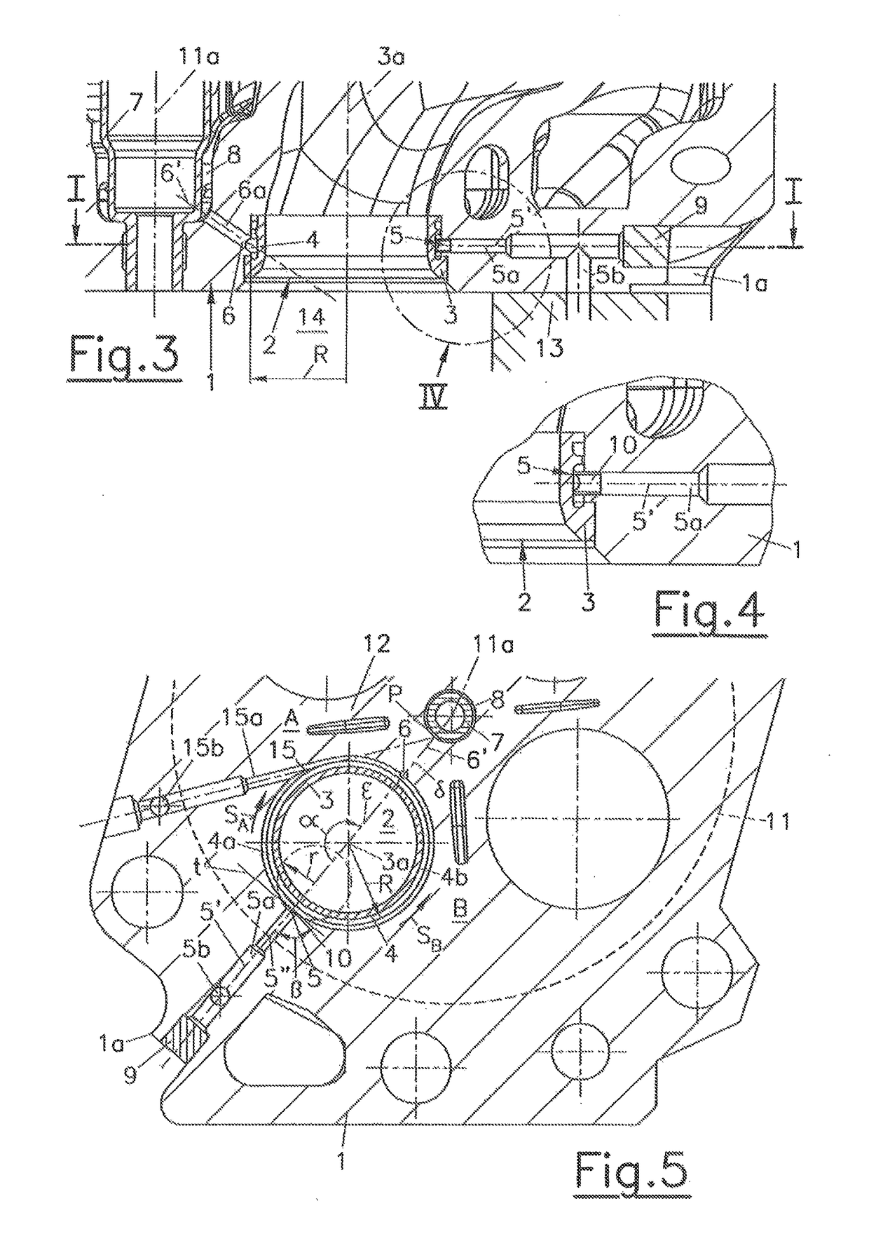
[0036]FIG. 2 shows a second embodiment which differs from FIG. 1 in such a way that the indentation 10 is arranged asymmetrically in relation to a meridian plane ε extending through the centre 5″ of the inlet 5 and / or a meridian plane δ of the valve seat ring 3 extending through the outlet 6. The flow losses during the incoming flow of the coolant into the cooling duct 4 are reduced on the one hand and an asymmetric division of quantities of the coolant is produced on the other hand into the two annular sections 4a, 4b of the cooling duct 4. Higher heat dissipation can thus be achieved on one side of the meridian plane ε and δ than on the other side. In particular, the heat dissipation is increased on the side of the meridian plane ε, δ in which the major part of the sickle-shaped indentation 10 is arranged. FIG. 3 and FIG. 4 show the arrangement in a sectional view in the meridian plane ε, δ, wherein the inlet 5 is shown in detail in FIG. 4.

third embodiment

[0037]FIG. 5 shows the cylinder head 1 in a third embodiment, wherein a tangential inlet 15 with a tangential inlet duct 15a is provided in addition to a radial inlet 5 having a radial inlet duct 5a. The tangential inlet duct 15a opens tangentially into the annular cooling duct 4. This leads to a pronounced highly asymmetrical coolant flow in the cooling duct 4, wherein a higher quantity of coolant flows according to the arrows SA, SB through the section 4a of the cooling duct 4 facing the exhaust valve bridge 12 than through the other section 4b that faces away, so that the cylinder head 1 is cooled more strongly on the side A of the Meridian plane ε and δ of the valve seat ring 3 than on the side B.


PUM


Abstract

The invention relates to a cylinder head (1) for an internal combustion engine having at least one cylinder, having at least one valve seat ring (3) for a lifting valve, wherein the valve seat ring (3) is surrounded by an annular cooling duct (4) for a coolant that is at least partly molded into the cylinder head (1), wherein the cooling duct (4) at least partly surrounds the valve seat ring and extends between an inlet (5, 15, 25) and at least one outlet (6). In order to reduce the valve wear, provision is made for a plurality of inlets (5, 15, 25) to open into the cooling duct (4), wherein the inlets (5, 15, 25) are preferably arranged asymmetrically in relation to a meridian plane (δ) of the valve seat ring (3) through the outlet (6).

Description

BACKGROUND OF THE INVENTIONField of the Invention[0001]The invention relates to a cylinder head for an internal combustion engine, comprising at least one cylinder, at least one valve seat ring for a lifting valve, wherein the valve seat ring is surrounded by an annular cooling duct for a coolant that is at least partly moulded into the cylinder head, wherein the cooling duct at least partly surrounds the valve seat ring and extends between an inlet and at least one outlet.The Prior Art[0002]A valve seat ring for a reciprocating internal combustion engine arranged in a cylinder head is known from WO 08 / 059108 A, wherein a circumferential cooling duct is arranged in the valve seat ring, which cooling duct extends between an inlet and an outlet for a coolant.[0003]Current high-performance internal combustion engines comprise regions that are highly thermally stressed in the area of the exhaust valve bridges between the exhaust valve seats. These regions are at risk especially concerni...

Claims


Application Information

Patent Timeline
IPC IPC(8): F02F1/40F02F1/36F01P3/14F01L3/22
CPCF02F1/36F01L3/22F02F1/40F01P3/14F01L2810/01F01L3/12
Inventor POSCHL, ROBERTKNOLLMAYR, CHRISTOF
Owner AVL LIST GMBH
Learn More