
Air filter for a combustion machine

An air filter and internal combustion engine technology, applied in the field of fixed power equipment and air filters, can solve the problems of expensive maintenance and repair work, disadvantages, etc., and achieve the effect of small structure volume and flow loss, and reduce noise level.

Inactive Publication Date: 2010-01-27
GE JENBACHER
View PDF0 Cites 4 Cited by
  • Summary
  • Abstract
  • Description
  • Claims
  • Application Information

AI Technical Summary

Problems solved by technology

[0005] Such an arrangement is relatively expensive and proves to be disadvantageous for maintenance and repair work

Method used


Image

  • Air filter for a combustion machine
  • Air filter for a combustion machine
  • Air filter for a combustion machine

Examples


Embodiment Construction

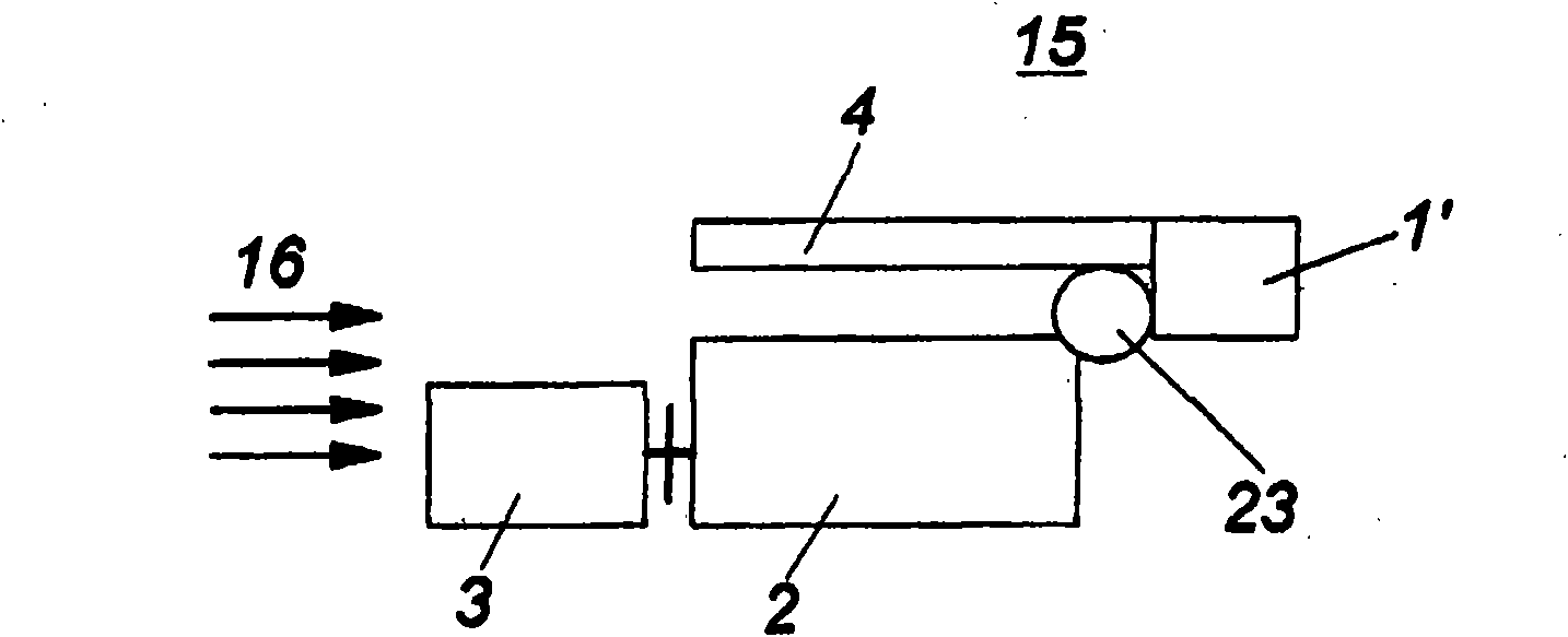
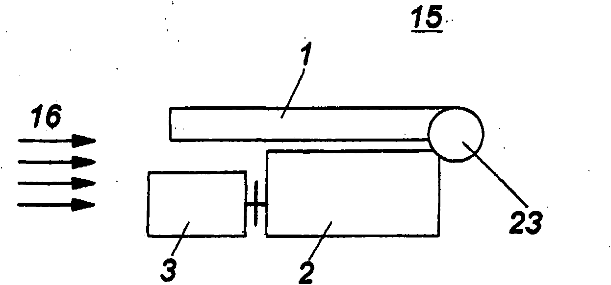
[0026] Figure 1a with 1bIn each case, a stationary power plant 15 according to the prior art is shown, which is arranged in a machine room, not shown in more detail. The stationary power plant 15 includes an internal combustion engine 2 and a generator 3 , the internal combustion engine 2 driving the generator 3 . By way of example, the internal combustion engine is a gas engine. as by Figure 1a As is evident, air 16 (from the left in the plane of the drawing) flows around generator 3 and internal combustion engine 2 . A supercharging device 23 is now arranged on the internal combustion engine 2 , in which the intake air 16 is compressed. If the intake air 16 is now drawn in directly in the area of ​​the supercharging device 23 , the hot air discharged from the generator 3 is also drawn in, which can lead to an increase in the temperature of the air drawn in via the intake duct 4 up to 20°, This results in a severe reduction in power and efficiency of the internal combust...


PUM


Abstract

An air filter for a combustion machine including a housing with a flow passage and a filter insert, wherein said filter insert subdivides the flow passage into an intake flow passage with an air inlet opening and into a discharge flow passage with an air outlet opening, wherein the filter insert has an air inlet surface which extends at least region-wise over the length of the filter insert along the air flow direction, wherein said filter insert has at least two successive filter elements, wherein the outside diameter or diameters of said filter elements, is or are different.

Description

technical field [0001] The invention relates to an internal combustion engine with an intake manifold and an air filter. The invention also relates to an air filter for an internal combustion engine, comprising a housing with a flow channel and a filter insert, wherein the filter insert divides the flow channel into an inlet channel with an air inlet and an air outlet the outflow channel. Finally, the invention relates to a stationary power plant comprising an internal combustion engine and a generator, the generator being drivable by the internal combustion engine. Background technique [0002] Filtration of intake air is a commonly performed practice in internal combustion engines or internal combustion engines, and it is used in virtually any internal combustion engine. In many applications, a porous filter is used for filtering the air, wherein the cross-section of the pores through which the air to be filtered flows is designed according to the required filter class. ...

Claims


Application Information

Patent Timeline
Patent Type & Authority Applications(China)
IPC IPC(8): F02M35/04
CPCF02M35/024B01D46/0021B01D2279/60B01D46/2411B01D46/60
Inventor F·格鲁贝尔G·卡特赖因J·朗
Owner GE JENBACHER
Learn More