Impingement system in drying section of paper machine or like

A technology of impact system and paper machine, which is applied in the direction of paper machine, dryer department, paper making, etc., and can solve the problem that it cannot be installed on the base normally

Inactive Publication Date: 2006-05-03
METSO PAPER INC
View PDF2 Cites 0 Cited by
  • Summary
  • Abstract
  • Description
  • Claims
  • Application Information

AI Technical Summary

Problems solved by technology

Due to the large size, such an air impingement roll cannot even fit properly in the basement under this paper machine when modernizing the paper machine

Method used


Image

  • Impingement system in drying section of paper machine or like
  • Impingement system in drying section of paper machine or like
  • Impingement system in drying section of paper machine or like

Examples


Embodiment Construction

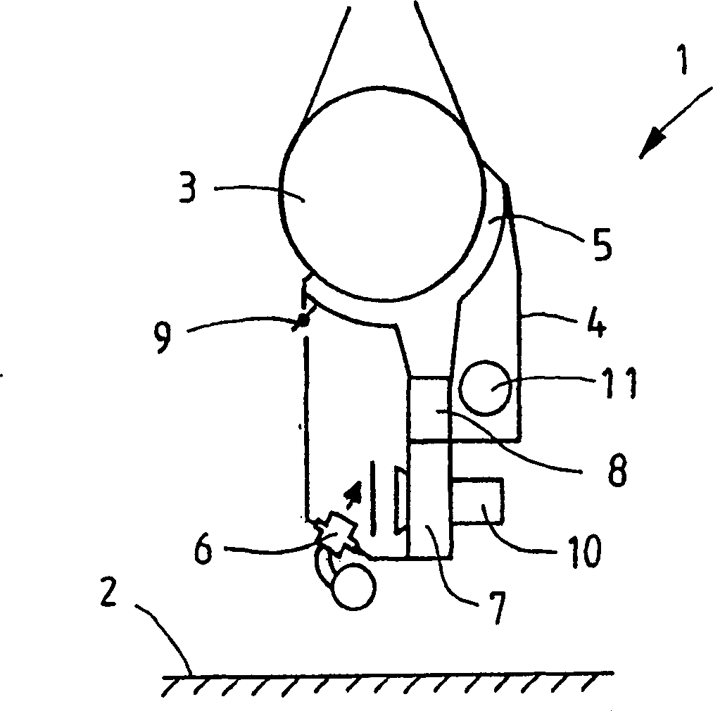
[0030] figure 1 The number 1 in the figure indicates the air impingement system of the present invention located in the bed space below a paper machine, and the floor of the bed space is indicated by the number 2 . The diameter of the drying roll 3 is in many cases about 1.5 m, ie about 1.5-2 m, and the height of the bed space below the paper machine is usually 5-8 m. The air impingement system comprises a hood 4 located mainly below the drying roll 3, but on the rear side of the drying roll 3, so that the shredded paper can fall freely. Shredding causes web interruptions, but usually it only causes quality deviations which are also harmful. The cover 4 is at most 5m high, preferably only 1.5-2.5m high. The area over which the cover covers the drying roller should be at least no greater than 180° so that the cover can be removed from its working position when required, in particular without using any troublesome mechanisms. This is why it is recommended that the maximum cov...


PUM


Abstract

The invention relates to an air impingement system arranged outside the jacket of an air impingement roll in the drying section of a paper machine or the like for heating and drying a web travelling around the said air impingement roll. The air impingement system comprises a mainly closed hood, which has control means for directing air onto the paper web. From the hood, air is directed by blowing with at least one fan to the blower nozzles and back again into the said hood as a circulation air process, and the system incorporates at least one heating device for heating the air. The air impingement system's hood and its said equipment are used in conjunction with an air impingement roll, which is of the size of approximately 1.5-2 m in diameter. The hood of the air impingement roll is at maximum 5 m high, preferably only 1.5-2.5 m high.

Description

technical field [0001] The invention relates to an air impingement system arranged in the dryer section of a paper machine for heating and drying a paper web conveyed on an air impingement roll in the dryer section of a paper machine. Background technique [0002] A solution for using an air drying system in the drying section of a paper machine is found in the applicant's patent US 6,138,380, in which an air impingement roll having a diameter much larger than normal drying rolls is used. Due to their large size, such air impingement rolls could not even fit properly in the bed below the paper machine when it was being modernized. This structure is sensitive to problems caused by paper shredding. Drying can also be done more efficiently by the method described in US Pat. No. 6,148,538, although in this configuration the efficiency of the condensing means for dehumidification need not be very high. Contents of the invention [0003] It is an object of the present inventio...

Claims


Application Information

Patent Timeline
Patent Type & Authority Patents(China)
IPC IPC(8): D21F5/18D21F5/04
CPCD21F5/044D21F5/18
Inventor H·松德奎斯特J·努尔米H·彼得森
Owner METSO PAPER INC
Why Eureka
Try Eureka