Flexible circuit electrode array with wire or film support

a flexible circuit and electrode array technology, applied in the field of neural stimulation, can solve the problems of increased electrical resistance retinal ischemia and hemorrhage, electric field dispersion, etc., and achieve the effect of reducing the interface between the array and the retina, hemorrhage, and reducing the risk of ischemia

Active Publication Date: 2018-01-09
CORTIGENT INC +1
View PDF13 Cites 0 Cited by
  • Summary
  • Abstract
  • Description
  • Claims
  • Application Information

AI Technical Summary

Benefits of technology

[0015]The pressure applied against the retina, or other neural tissue, by an electrode array is critical. Too little pressure causes increased electrical resistance between the array and retina, along with electric field dispersion. Too much pressure may block blood flow causing retinal ischemia and hemorrhage. Pressure on the neural retina may also block axonal flow or cause neuronal atrophy leading to optic atrophy. Common flexible circuit fabrication techniques such as photolithography generally require that a flexible circuit electrode array be made flat. Since the retina is spherical, a flat array will necessarily apply more pressure near its edges, than at its center. Further, the edges of a flexible circuit polymer array may be quite sharp and cut the delicate retinal tissue. With most polymers, it is possible to curve them when heated in a mold. By applying the right amount of heat to a completed array, a curve can be induced that matches the curve of the retina. With a thermoplastic polymer such as liquid crystal polymer, it may be further advantageous to repeatedly heat the flexible circuit in multiple molds, each with a decreasing radius. Further, it is advantageous to add material along the edges of a flexible circuit array to make the edges less sharp and / or more compliant. Particularly, it is advantageous to add material that is more compliant than the polymer used for the flexible circuit array so that the edges of the array conform more readily to the retina and are therefore less likely to cause damage to the retina.
[0016]It is further advantageous to provide a fold or twist in the flexible circuit array at the point where it passes through the sclera in order to reduce the size of the array cable in the trans-scleral region to minimize the possibility of leakage at the sclerotomy. Another reason for folding or twisting the array cable at the sclerotomy is to flip the array head so the electrodes are facing the retina. Additional material may be added inside and outside the fold to promote a good seal with the scleral tissue.
[0021]Another aspect of the invention is a method of applying an additional layer or two layers of softer polymer, such as silicone, over said flexible circuit to provide a softer interface to the retina. A support may be embedded in said softer polymer layer(s) to provide greater shape control and pressure uniformity on the retina.

Problems solved by technology

Too little pressure causes increased electrical resistance between the array and retina, along with electric field dispersion.
Too much pressure may block blood flow causing retinal ischemia and hemorrhage.
Pressure on the neural retina may also block axonal flow or cause neuronal atrophy leading to optic atrophy.
Further, the edges of a flexible circuit polymer array may be quite sharp and cut the delicate retinal tissue.

Method used


Image

  • Flexible circuit electrode array with wire or film support

Examples


Embodiment Construction

[0105]The following description is of the best mode presently contemplated for carrying out the invention. This description is not to be taken in a limiting sense, but is made merely for the purpose of describing the general principles of the invention. The scope of the invention should be determined with reference to the claims.

[0106]The present invention is generally directed to neural stimulation and more specifically to an improved electrode array for neural stimulation with a support including at least one wire or film or foil embedded in the array.

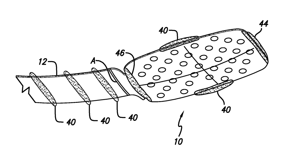
[0107]FIG. 1 shows a perspective view of the implanted portion of the preferred retinal prosthesis. A flexible circuit 1 includes a flexible circuit electrode array 10 which is mounted by a retinal tack (not shown) or similar means to the epiretinal surface. The flexible circuit electrode array 10 is electrically coupled by a flexible circuit cable 12, which pierces the sclera and is electrically coupled to an electronics package 14,...


PUM


Abstract

The disclosure relates to a flexible circuit electrode array comprising: a polymer base layer; metal traces deposited on said polymer base layer, including electrodes suitable to stimulate neural tissue; a polymer top layer deposited on said polymer base layer and said metal traces; and at least one support embedded in said array. The disclosure further relates to a flexible circuit electrode array comprising: a polymer base layer; metal traces deposited on said polymer base layer, including electrodes suitable to stimulate neural tissue; a polymer top layer deposited on said polymer base layer and said metal traces; and a folded flexible circuit cable connecting the electrode array with an interconnection pad. The disclosure further relates to a method of making a flexible circuit electrode array comprising: depositing a polymer base layer; depositing metal on said polymer base layer; patterning said metal to form metal traces; depositing a polymer top layer on said polymer base layer and said metal traces; heating said flexible circuit electrode array in a mold to form a three dimensional shape in said flexible circuit electrode array, embedding a support at least in the base layer, top layer or between the base and top layer, and / or folding a flexible circuit cable at least once connecting the electrode array with an interconnection pad the array.

Description

CROSS-REFERENCE TO RELATED APPLICATIONS[0001]This application claims the benefit of U.S. Provisional Application No. 60 / 901,907, “Flexible Circuit Electrode Array with Wire or Film Support”, filed Feb. 16, 2007 and this application claims the benefit of U.S. Provisional Application No. 60 / 901,947, “Flexible Circuit Electrode Array with a Folded Flexible Array Cable”, filed Feb. 16, 2007, the disclosures of both are incorporated herein by reference.GOVERNMENT RIGHTS NOTICE[0002]This invention was made with government support under grant No. R24EY12893-01, awarded by the National Institutes of Health. The government has certain rights in the invention.FIELD OF THE INVENTION[0003]The present invention is generally directed to neural stimulation and more specifically to an improved electrode array for neural stimulation with a support including at least one wire or film or foil embedded in the array and to flexible circuit electrode array with a folded flexible array cable.BACKGROUND OF...

Claims


Application Information

Patent Timeline
Patent Type & Authority Patents(United States)
IPC IPC(8): A61N1/00A61N1/05H05K1/03H05K1/11
CPCA61N1/0543A61N1/0541H05K1/118H05K1/0393A61N1/05
Inventor GREENBERG, ROBERT J.DE JUAN, EUGENEHUMAYUN, MARK S.MCCLURE, KELLY H.TALBOT, NEIL HAMILTONNEYSMITH, JORDAN MATTHEWMECH, BRIAN V.LITTLE, JAMES SINGLETONKHALDI, MOHAMED
Owner CORTIGENT INC
Why Eureka
Try Eureka