CVI densification installation including a high capacity preheating zone

a densification installation and high-capacity technology, applied in the field of ovens, can solve the problems of increasing the complexity and the overall size of the installation, difficult to control the temperature of the reactive gas in the preheater chamber, and the cost of investment in chemical vapor infiltration processes, so as to enhance the productivity of the installation and increase the volume

Active Publication Date: 2017-12-19
SAFRAN CERAMICS SA
View PDF14 Cites 7 Cited by
  • Summary
  • Abstract
  • Description
  • Claims
  • Application Information

AI Technical Summary

Benefits of technology

[0011]An object of the invention is to propose a design for a thermochemical treatment installation that enables a gas stream to be preheated to a determined temperature while minimizing temperature differences between the center and the periphery of the installation at the outlet from the preheater chamber, and to do this without needing to increase its volume in order to enhance the productivity of the installation.
[0013]By using walls between the distribution trays, the heating capacity of the preheater chamber is increased firstly by increasing heat exchange by convection and secondly by lengthening the travel path and consequently the transit time of the gas through the preheater chamber. The uniformity of the temperature profile of the reactive gas leaving the preheater chamber is also improved, and this applies regardless of the diameter of the installation. With the installation of the invention, it is possible to obtain preheating performance that is equivalent or even improved, while using a preheater chamber presenting a volume that is smaller than the volume of a chamber not having such walls. Alternatively, for equal preheater chamber volume, with a preheater chamber having walls of the invention, the performance that is obtained in terms of temperature and uniformity of heating is much improved in comparison with a preheater chamber not having such walls.
[0014]According to a characteristic of the installation of the invention, the distribution trays are disk-shaped and least some of the walls extend between said trays in a radial direction. Such an arrangement serves to guide the flow of the gas stream over the entire surface of the trays and thus maximize heat transfer.
[0015]According to another characteristic of the installation of the invention, at least some of the walls present an undulating shape, thus making it possible to lengthen the walls, and consequently to lengthen the heat exchange area for the gas stream.
[0016]According to another characteristic of the installation of the invention, the walls present thermal conductivity that is greater in a direction parallel to the distribution trays than in a direction perpendicular to said perforated trays. This makes it possible to define anistropic heat conduction between the distribution trays, thereby creating partial thermal decoupling between the cold portion of the installation and the loading zone, while also increasing the heating capacity of the preheater chamber. Under such circumstances, the walls may be made of graphite or of composite material having fiber reinforcement densified by a matrix, with the reinforcing fibers extending for the most part in a direction parallel to the distribution trays.
[0017]According to another characteristic of the installation of the invention, the number of walls is greater in the vicinity of the peripheries of the distribution trays than in the centers of said trays. This optimizes the distribution of the walls between the trays and further increases the heat exchange area for the gas stream.

Problems solved by technology

Such preheater means increase the complexity and the overall size of the installation.
Nevertheless, although the preheater chamber enables the reactive gas to be heated prior to being introduced into the loading zone, it is difficult to control the temperature of the reactive gas in the preheater chamber so that it is uniform radially, in particular in installations of large diameter.
Unfortunately, treatments such as chemical vapor infiltration processes require investments that are expensive on an industrial scale, and they take a long time to perform.

Method used


Image

  • CVI densification installation including a high capacity preheating zone
  • CVI densification installation including a high capacity preheating zone
  • CVI densification installation including a high capacity preheating zone

Examples


Embodiment Construction

[0025]The invention applies to any type of installation or oven used for performing heat treatment and in which the gas used in the treatment is preheated in a preheater chamber prior to being introduced into the treatment or loading zone of the installation. Such installations are used in particular for performing thermochemical treatments such as carburizing parts or densifying porous substrates by chemical vapor infiltration.

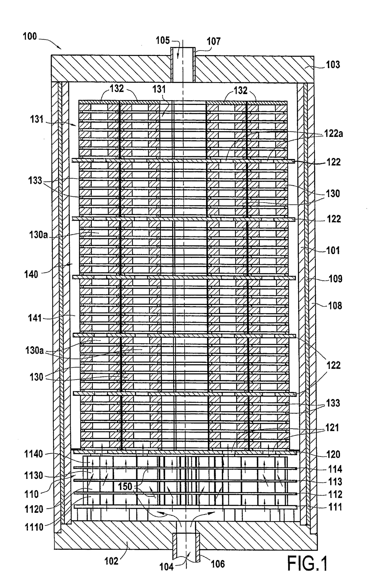
[0026]A first embodiment of a densification oven is described with reference to FIGS. 1 to 3. FIG. 1 is a diagram showing an installation 100 for densification by chemical vapor infiltration that is defined by a cylindrical side wall 101, a bottom wall 102, and a top wall 103.

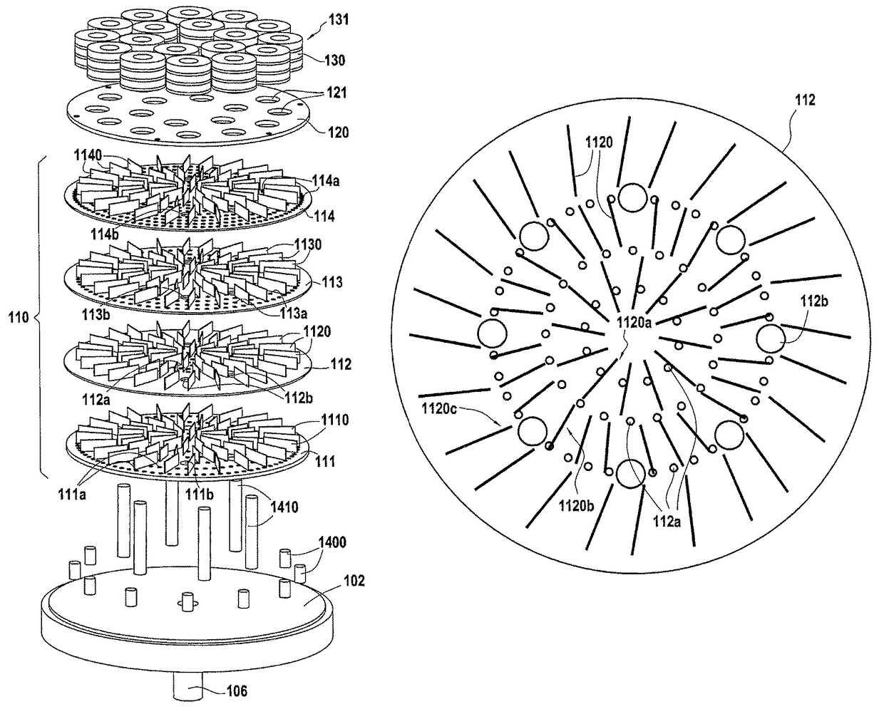
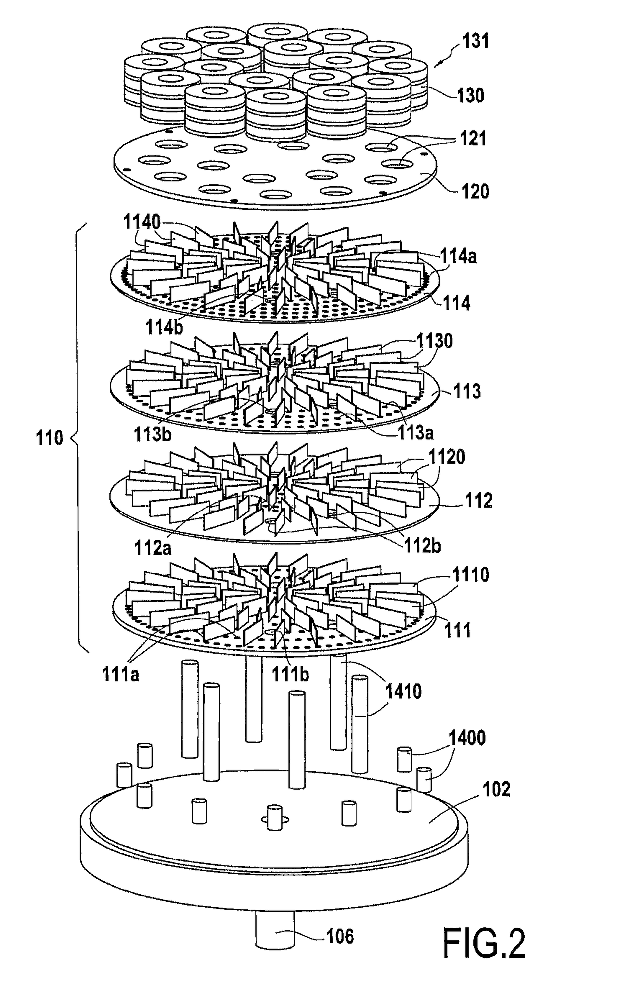
[0027]A gas preheater chamber 110, of structure that is described in detail below, extends between the bottom 102 of the oven and a loading tray 120. A pipe 106 connects the reactive gas inlet 104 to the preheater chamber 110 through the bottom 102.

[0028]Substrates 130 for densifying are...


PUM

PropertyMeasurementUnit
temperatureaaaaaaaaaa
shapeaaaaaaaaaa

Abstract

A thermochemical treatment installation includes a reaction chamber, at least one gas inlet, and a gas preheater chamber situated between the gas inlet and the reaction chamber. The preheater chamber has a plurality of perforated distribution trays held spaced apart one above another. The preheater chamber also includes, between at least the facing distribution trays, a plurality of walls defining flow paths for a gas stream between said trays.

Description

CROSS-REFERENCE TO RELATED APPLICATIONS[0001]This is the U.S. National Stage of PCT / FR2015 / 050546, filed Mar. 5, 2015, which in turn claims priority to French Patent Application No. 1452151, filed Mar. 14, 2014, the entire contents of all applications are incorporated herein by reference in their entireties.BACKGROUND OF THE INVENTION[0002]The invention relates to installations or ovens used for performing heat treatment, and in which the gas used in the treatment is preheated prior to being introduced into the treatment chamber of the installation. Such installations are used in particular for performing thermochemical treatments, such as carburizing parts or densifying porous substrates by chemical vapor infiltration.[0003]A field of application of the invention is that of making parts out of thermostructural composite material, i.e. out of composite material that possesses both mechanical properties that make it suitable for constituting structural parts and also the ability to c...

Claims


Application Information

Patent Timeline
Patent Type & Authority Patents(United States)
IPC IPC(8): C23C16/46F28F3/08C23C16/458F27D99/00C23C16/455F28C3/00C04B35/80B01J6/00B01J8/02F28F13/06C23C16/452F27B5/16F27D7/06C23C16/04F28D21/00
CPCC23C16/46B01J8/0285C04B35/80C23C16/045C23C16/452C23C16/4557C23C16/4583C23C16/45591F27B5/16F27D7/06F27D99/0001F28C3/005F28F3/086F28F13/06B01J6/00F28D2021/0022B01J2208/00407B01J2208/00415B01J2208/00433B01J2208/00469B01J2208/00884B01J2208/00938B01J2219/00006C04B2235/425C04B2235/5268C23C16/455C04B35/83C04B2235/614C04B35/56C23C8/20F28F3/08C23C16/04
Inventor DELPERIER, BERNARDPOTIN, JEAN-FRANCOISSOULIGNAC, SOPHIE
Owner SAFRAN CERAMICS SA
Why Eureka
Try Eureka