
System and method of storing and/or transferring high level radioactive waste

a high-level radioactive waste and waste technology, applied in the field of systems and methods for storing high-level waste, can solve the problems of large heat generation, high radioactivity of spent nuclear fuel, and large volume, and require great car

Active Publication Date: 2017-11-28
HOLTEC INT
View PDF7 Cites 11 Cited by
  • Summary
  • Abstract
  • Description
  • Claims
  • Application Information

AI Technical Summary

Benefits of technology

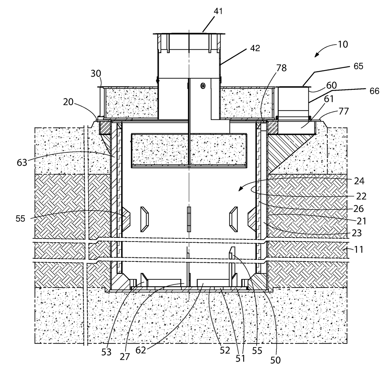
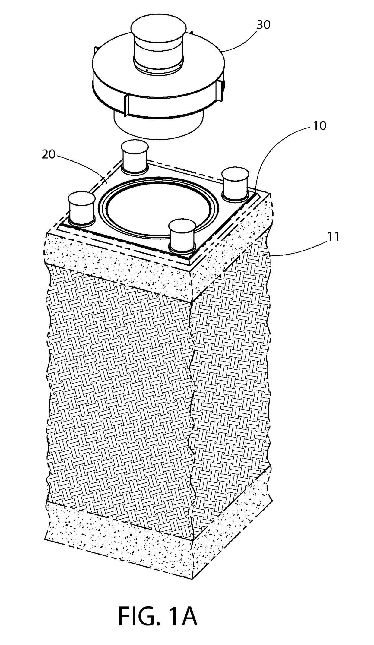
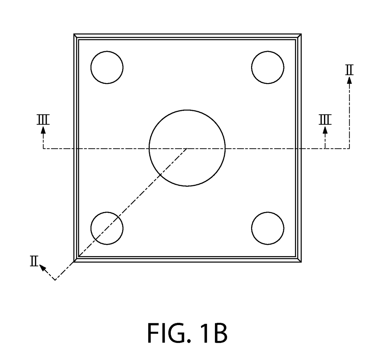
The present invention relates to a module for storing high-level radioactive waste. The module has an outer shell and an inner shell with a space in between them. The module has at least one divider that creates inlet passageways through the space, each inlet duct connecting to the bottom of the cavity and being surrounded by inlet walls with a minimum of 60% open area. The invention also includes an outlet duct connecting the cavity to the ambient atmosphere. The module can be used in combination with other modules and has advantages such as maintaining air pressure and independence between inlet ducts.

Problems solved by technology

Upon removal, this spent nuclear fuel is still highly radioactive and produces considerable heat, requiring that great care be taken in its packaging, transporting, and storing.
VVOs stand above ground and are typically cylindrical in shape and extremely heavy, weighing over 150 tons and often having a height greater than 16 feet.
The effect of wind on the thermal performance of a ventilated system can also be a serious drawback that, to some extent, afflicts all systems in use in the industry at the present time.
Storage VVO's with only two inlet or outlet ducts are especially vulnerable.
While axisymmetric air inlet and outlet ducts behave extremely well in quiescent air, when the wind is blowing, the flow of air entering and leaving the system is skewed, frequently leading to at reduced heat rejection capacity.

Method used


Image

  • System and method of storing and/or transferring high level radioactive waste
  • System and method of storing and/or transferring high level radioactive waste
  • System and method of storing and/or transferring high level radioactive waste

Examples


Embodiment Construction

[0033]The description of illustrative embodiments according to principles of the present invention is intended to be read in connection with the accompanying drawings, which are to be considered part of the entire written description. In the description of embodiments of the invention disclosed herein, any reference to direction or orientation is merely intended for convenience of description and is not intended in any way to limit the scope of the present invention. Relative terms such as “lower,”“upper,”“horizontal,”“vertical,”“above,”“below,”“up,”“down,”“left,”“right,”“top” and “bottom” as well as derivatives thereof (e.g., “horizontally,”“downwardly,”“upwardly,” etc.) should be construed to refer to the orientation as then described or as shown in the drawing under discussion. These relative terms are for convenience of description only and do not require that the apparatus be constructed or operated in a particular orientation unless explicitly indicated as such. Terms such as ...


PUM


Abstract

A module for storing high level radioactive waste includes an outer shell, having a hermetically closed bottom end, and an inner shell forming a cavity and being positioned inside the outer shell to form a space therebetween. At least one divider extends from the top to the bottom of the inner shell to create a plurality of inlet passageways through the space, each inlet passageway connecting to a bottom portion of the cavity. A plurality of inlet ducts each connect at least one of the inlet passageways and ambient atmosphere, and each includes an inlet duct cover affixed atop a surrounding inlet wall, the inlet wall being peripherally perforated. A removable lid is positioned atop the inner shell and has at least one outlet passageway connecting the cavity and the ambient atmosphere, the lid and the top of the inner shell being configured to form a hermetic seal therebetween.

Description

CROSS REFERENCE TO RELATED APPLICATIONS[0001]The present application is a U.S. national stage application under 35 U.S.C. 371 of PCT Application No. PCT / US2013 / 037228, filed on Apr. 18, 2013, which claims the benefit of U.S. Provisional Patent Application 61 / 625,869, filed Apr. 18, 2012, the disclosures of which are incorporated herein by reference in their entireties.FIELD OF THE INVENTION[0002]The field of the present invention relates systems and methods for storing high level waste (“HLW”), such as spent nuclear fuel, in ventilated vertical modules.BACKGROUND OF THE INVENTION[0003]The storage, handling, and transfer of HLW such as spent nuclear fuel, requires special care and procedural safeguards. For example, in the operation of nuclear reactors, it is customary to remove fuel assemblies after their energy has been depleted down to a predetermined level. Upon removal, this spent nuclear fuel is still highly radioactive and produces considerable heat, requiring that great care ...

Claims


Application Information

Patent Timeline
Patent Type & Authority Patents(United States)
IPC IPC(8): G21F5/005G21C19/40G21F7/015G21F9/34
CPCG21F5/005G21F9/34G21F7/015G21C19/40G21F7/00Y02E30/30G21F5/10G21F5/12
Inventor SINGH, KRISHNA P.
Owner HOLTEC INT
Learn More