
Heated cleaning articles using a reactive metal and saline heat generator

a technology of reactive metal and saline, which is applied in the direction of carpet cleaners, cleaning using liquids, lighting and heating apparatus, etc., can solve the problems that heat generators have not been adapted for use in cleaning articles, and achieve the effects of convenient, safe, and self-heating cleaning articles

Active Publication Date: 2017-11-28
THE CLOROX CO
View PDF45 Cites 4 Cited by
  • Summary
  • Abstract
  • Description
  • Claims
  • Application Information

AI Technical Summary

Benefits of technology

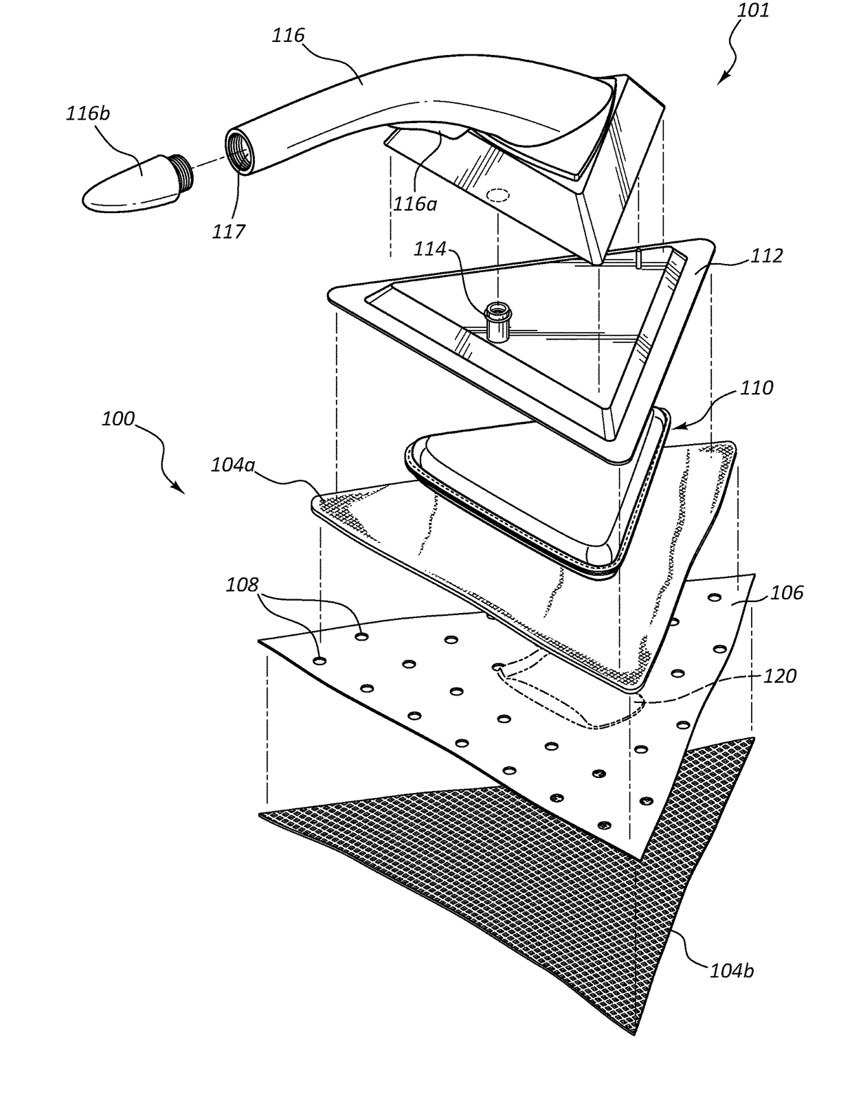
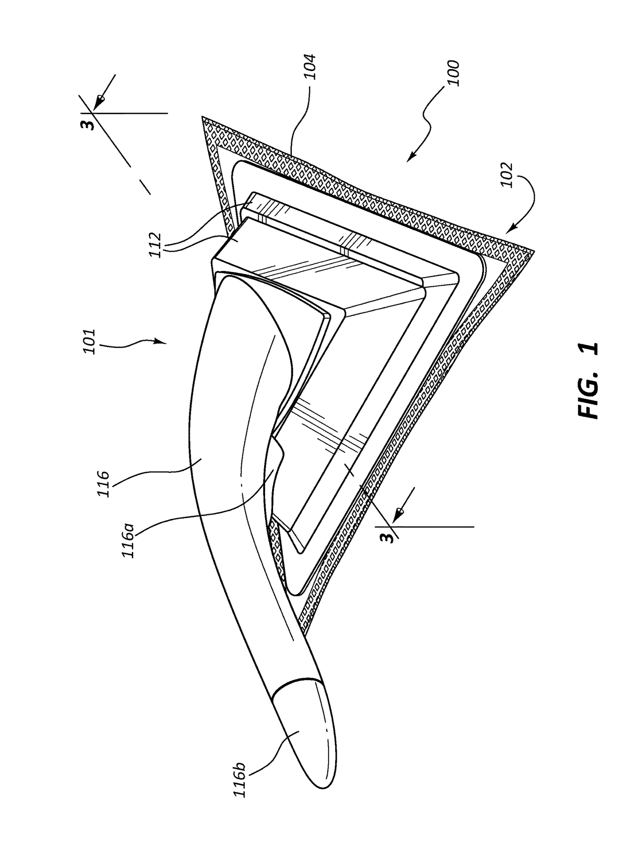
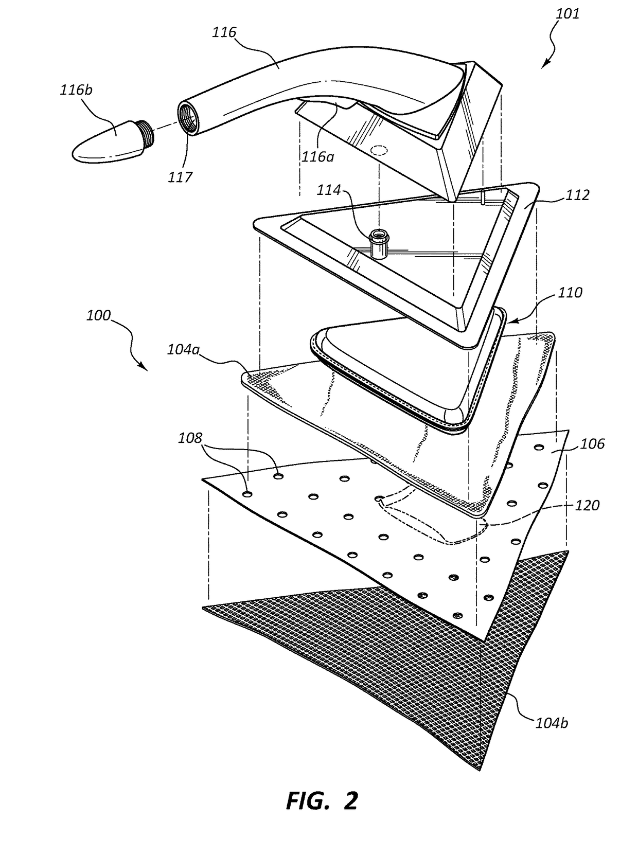
The present invention relates to a cleaning article that includes a heat engine using a reactive metal and a salt water composition. This invention allows for the cleaning article to generate heat and improve the efficacy of cleaning compositions and the cleaning substrate itself. The reactive metal and salt water composition can be separated from each other to prevent premature reaction between them, and can be activated when contacted with water or saline solution. The invention provides a convenient, safe, and self-heating cleaning article for various cleaning applications.

Problems solved by technology

Although there exist various products that employ heat generators that use exothermic reactions to generate heat (e.g., in heating MRE meals, hand and boot warmers, and the like), heat generators have not been adapted for use in cleaning articles.
Use of such a reactive metal and salt water heat generator with a cleaning article presents a number of difficulties to be addressed in order to create a product safe for consumer use.
For example, some such difficulties may include the ability to provide control over the amount of water or saline added to the reactive metal, control of temperatures achieved by the heat engine, control over directional flow of steam water vapor and / or other vapors generated during use, and otherwise ensuring that the heated cleaning article is safe for consumer use.

Method used


Image

  • Heated cleaning articles using a reactive metal and saline heat generator
  • Heated cleaning articles using a reactive metal and saline heat generator
  • Heated cleaning articles using a reactive metal and saline heat generator

Examples


Embodiment Construction

I. Definitions

[0026]Before describing the present invention in detail, it is to be understood that this invention is not limited to particularly exemplified systems or process parameters that may, of course, vary. It is also to be understood that the terminology used herein is for the purpose of describing particular embodiments of the invention only, and is not intended to limit the scope of the invention in any manner.

[0027]All publications, patents and patent applications cited herein, whether supra or infra, are hereby incorporated by reference in their entirety to the same extent as if each individual publication, patent or patent application was specifically and individually indicated to be incorporated by reference.

[0028]References herein to “one embodiment”, “one aspect” or “one version” of the invention include one or more such embodiment, aspect or version, unless the context clearly dictates otherwise.

[0029]The term “comprising,” which is synonymous with “including,”“cont...


PUM


Abstract

Cleaning articles including a heat engine incorporated therein. The cleaning article may include a substrate (e.g., a non-woven wipe) including one or more layers. The heat engine may be in the wipe or pad, and includes a reactive metal composition which upon contact with a salt water (e.g., saline) composition, reacts to produce heat. The cleaning article may thus produce water vapor and / or steam upon activation of the heat engine. A venting structure may be provided adjacent to or surrounding the heat engine that includes an impermeable material (e.g., impermeable to water and / or air or other gas), which includes one or more vents through the impermeable material. The venting structure directs water vapor and / or steam to a desired face of the cleaning article, away from the user. A heat barrier layer may insulate a user's hand from the generated heat, and / or a handle may be attachable to the pad.

Description

CROSS-REFERENCE TO RELATED APPLICATIONS[0001]This application claims priority to and the benefit of U.S. Provisional Patent Application No. 62 / 134,264 filed Mar. 17, 2015, entitled HEATED CLEANING ARTICLES USING A REACTIVE METAL AND SALINE HEAT GENERATOR, which is incorporated by reference in its entirety. This application also claims priority to and the benefit of U.S. Provisional Patent Application No. 62 / 140,384 filed Mar. 30, 2015, entitled HEATED CLEANING ARTICLES USING AN OXYGEN ACTIVATED HEAT GENERATOR, which is incorporated by reference in its entirety.BACKGROUND OF THE INVENTION[0002]1. The Field of the Invention[0003]The present invention relates to self-heated cleaning articles, e.g., a wipe or other cleaning substrate that includes a heat engine capable of producing heat that can be used in delivering a cleaning composition (which may simply be heated water) in a heated condition, to improve cleaning efficacy.[0004]2. Description of Related Art[0005]Cleaning devices and ...

Claims


Application Information

Patent Timeline
Patent Type & Authority Patents(United States)
IPC IPC(8): A47L13/16A47L13/17A47L13/22F24J1/00B08B3/10F24V30/00
CPCA47L13/225F24J1/00B08B3/10A47L13/17B08B2230/01C11D17/049F24V30/00
Inventor OUELLETTE, WILLIAM R.AZELTON, KERRYLIN, BRIANMAZUMDER, VISMADEBOCHOMOGO, MARIAPARRISH, BRYAN K.PETRIN, MICHAEL J.URIARTE, RICHARD J.
Owner THE CLOROX CO
Learn More