
Reticle chuck cleaner and reticle chuck cleaning method

a technology of reticle chuck and cleaning method, which is applied in the direction of cleaning process, microlithography exposure apparatus, instruments, etc., can solve the problems of euv scanner stopping for a longer time, pattern transfer onto a wafer is distorted, euv mask deformation to generate distortion on the patterned surface, etc., and achieve the effect of improving the operating ratio of euv exposure apparatus

Active Publication Date: 2017-11-07
KIOXIA CORP
View PDF11 Cites 1 Cited by
  • Summary
  • Abstract
  • Description
  • Claims
  • Application Information

AI Technical Summary

Benefits of technology

The present invention provides a cleaner for a reticle chuck in a vacuum chamber of an EUV exposure apparatus that can clean without exposing the chamber to the atmosphere, which improves the operating ratio of the apparatus.

Problems solved by technology

If foreign matters get caught between the chuck mechanism and the EUV mask, the EUV mask is deformed to generate distortion on the patterned surface.
This causes a problem that the pattern transferred onto a wafer is distorted.
In addition, since the chuck mechanism is located within a vacuum chamber, it is necessary to return the inside of the vacuum chamber to the atmosphere pressure before cleaning the vacuum chamber to remove foreign matters. in this case, the EUV scanner is stopped for a longer time, which is a major factor in decreasing the operating ratio of the EUV scanner.

Method used


Image

  • Reticle chuck cleaner and reticle chuck cleaning method
  • Reticle chuck cleaner and reticle chuck cleaning method
  • Reticle chuck cleaner and reticle chuck cleaning method

Examples


first embodiment

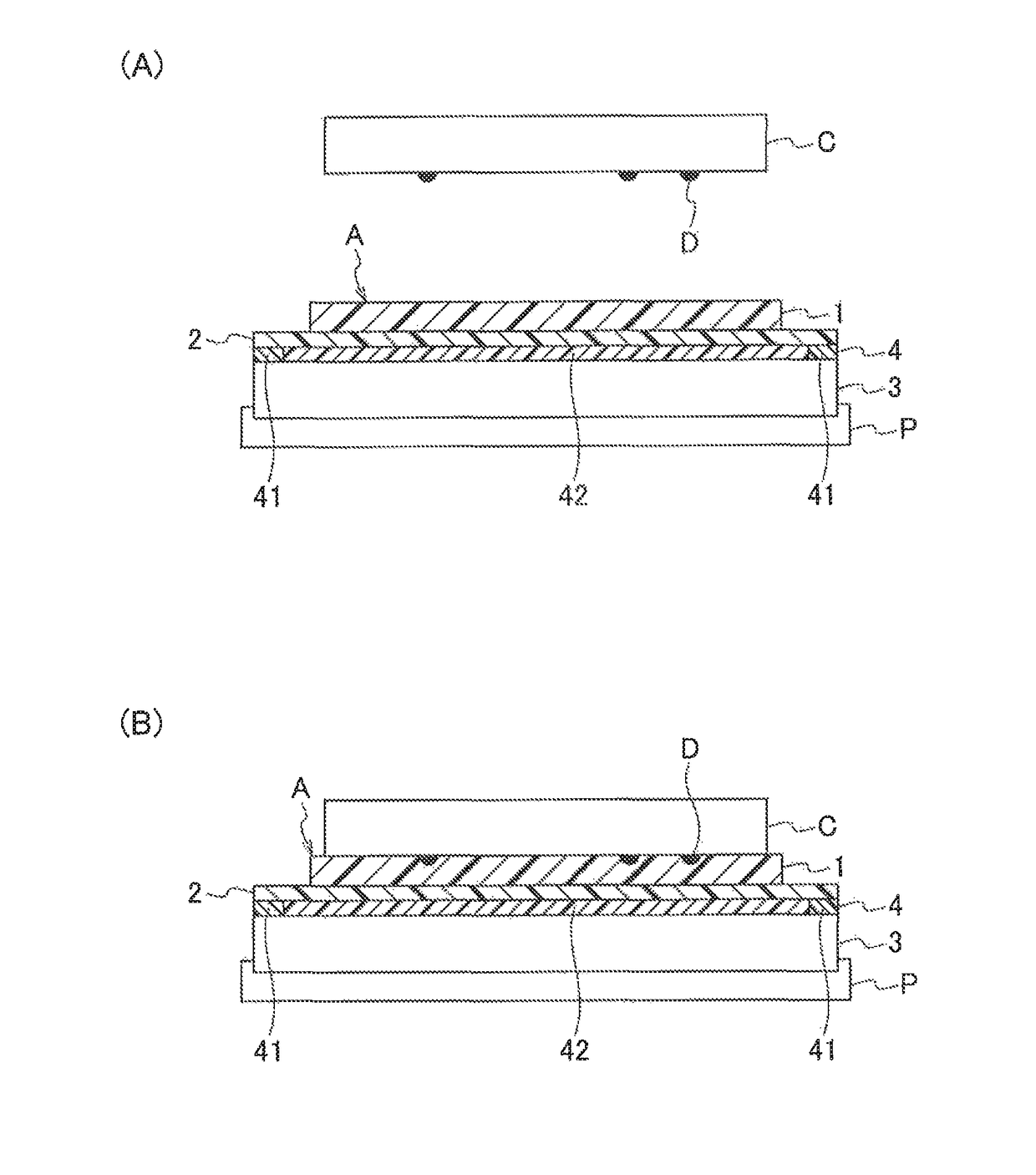
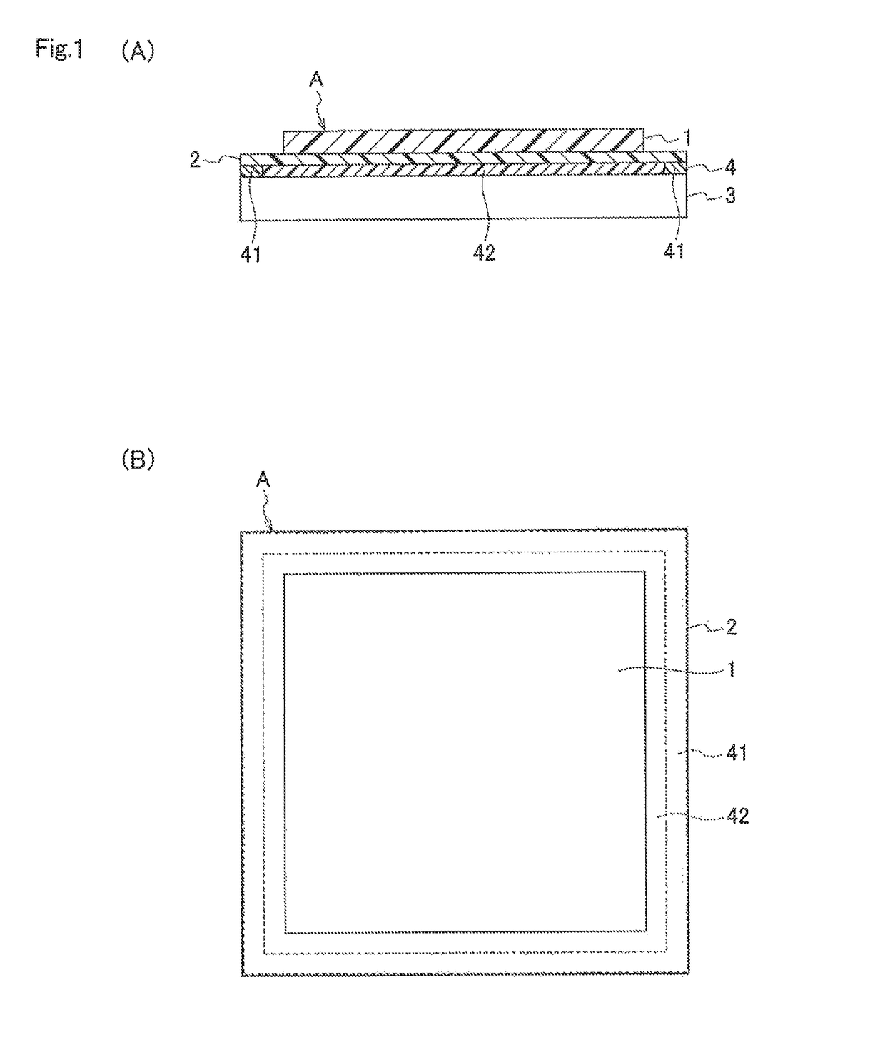
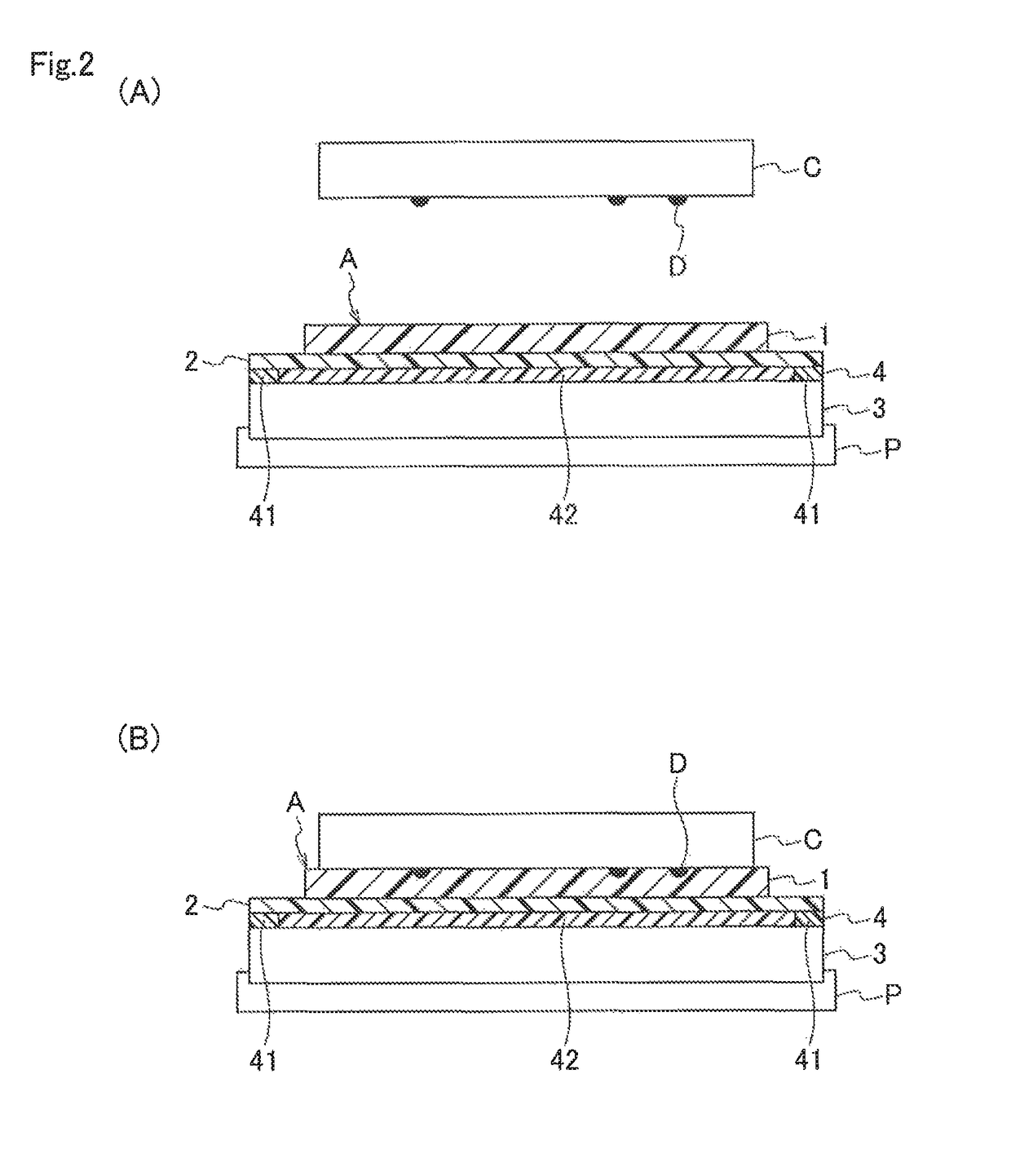
[0034]FIG. 1 is a schematic view for describing a configuration of a reticle chuck cleaner according to the present invention. FIG. 1(A) is a cross-sectional view and FIG. 1(B) is an upper view. The reticle chuck cleaner shown with reference code A includes an adhesive layer 1 to be adhered to a chuck region of a reticle chuck in an EUV exposure apparatus, a support layer 2 laminated on the adhesive layer 1, and a substrate 3 having a shape capable of being carried to the reticle chuck.

[0035]Reference numeral 4 denotes a partial adhesive layer that allows the support layer 2 and the substrate 3 to bond or adhere to each other in a region with adhesiveness 41 (hereinafter, referred to as “adhesive region 41”). The adhesive region 41 is provided at a circumferential portion of the partial adhesive layer 4, and the central part of the partial adhesive layer 4 (the part other than the adhesive region 41) is referred to as a region without adhesiveness 42 (hereinafter, referred to as “no...

second embodiment

[0065]FIG. 7 is a schematic view for describing a configuration of a reticle chuck cleaner according to the present invention. FIG. 7(A) is a cross-sectional view and FIG. 7(B) is an upper view. A reticle chuck cleaner shown with reference code B includes an adhesive layer 1 adhered to a chuck region of a reticle chuck in an EUV exposure apparatus, a support layer 2 laminated on the adhesive layer 1, and a substrate 3 having a shape capable of being carried to the reticle chuck.

[0066]The reticle chuck cleaner B is different from the reticle chuck cleaner A according to the first embodiment, in that the partial adhesive layer 4 allowing the support layer 2 and the substrate 3 to partially adhere or bond to each other (refer to FIG. 1) is not provided but the support layer 2 and the substrate 3 are bonded together by a double-faced tape 43. The double-faced tape 43 is inserted into between the support layer 2 and the substrate 3 so as to form a cross shape passing through the center o...


PUM

PropertyMeasurementUnit
wavelengthaaaaaaaaaa
thicknessaaaaaaaaaa
thicknessaaaaaaaaaa

Abstract

There is provided a reticle chuck cleaner A for cleaning a reticle chuck of an apparatus, as a reticle chuck cleaner that allows easy cleaning of a reticle chuck in a vacuum chamber of an apparatus without exposing the chamber to the atmosphere and contributes to improvement of the operating ratio of the apparatus, including: an adhesive layer 1 to be adhered to a chuck region of the reticle chuck; a support layer 2 laminated on the adhesive layer 1; and a substrate 3 having a shape capable of being carried to the reticle chuck, the support layer 2 and the substrate 3 being partially bonded together in an adhesive region 41 of a partial adhesive layer 4.

Description

TECHNICAL FIELD[0001]The present invention relates to reticle chuck cleaners and reticle chuck cleaning methods. More specifically, the present invention relates to reticle chuck cleaners or the like for cleaning a reticle chuck in an apparatus.BACKGROUND ART[0002]In recent years, there has been used EUV lithography with miniaturization of semiconductors. EUV light is as short in wavelength as 13.5 nm and thus is immediately attenuated in the atmosphere. Therefore, wafer exposure apparatuses (EUV scanners) using EUV light need to have an exposure optical system set up in vacuum. In this case, a reticle stage is placed in vacuum, and thus the chuck mechanism of an EUV mask cannot use a vacuum chuck system but employs an electrostatic chuck system. The electrostatic chuck system requires a chuck region of a larger area as compared to the vacuum chuck system, to obtain a specific retaining force. Accordingly, it is necessary to use the most part of the back surface of the EUV mask as a...

Claims


Application Information

Patent Timeline
Patent Type & Authority Patents(United States)
IPC IPC(8): B08B7/00G03F7/20
CPCB08B7/0028G03F7/70925G03F7/707B08B7/0014
Inventor KOBAYASHI, YOSHIHITOITOH, MASAMITSUINADA, TAROWATANABE, JUN
Owner KIOXIA CORP
Learn More