Eureka AIR delivers breakthrough ideas for toughest innovation challenges, trusted by R&D personnel around the world.

Electrical connector

a technology of electrical connectors and connectors, applied in the direction of coupling contact members, coupling device connections, electrical apparatus, etc., can solve the problems of reducing the production yield of electrical connectors, increasing the difficulty of stamping molding terminals, and retaining the terminal force, so as to avoid the effect of turning over, reducing the difficulty of assembly of products, and improving the yield of products

Active Publication Date: 2017-10-31
LOTES
View PDF20 Cites 13 Cited by
  • Summary
  • Abstract
  • Description
  • Claims
  • Application Information

AI Technical Summary

Benefits of technology

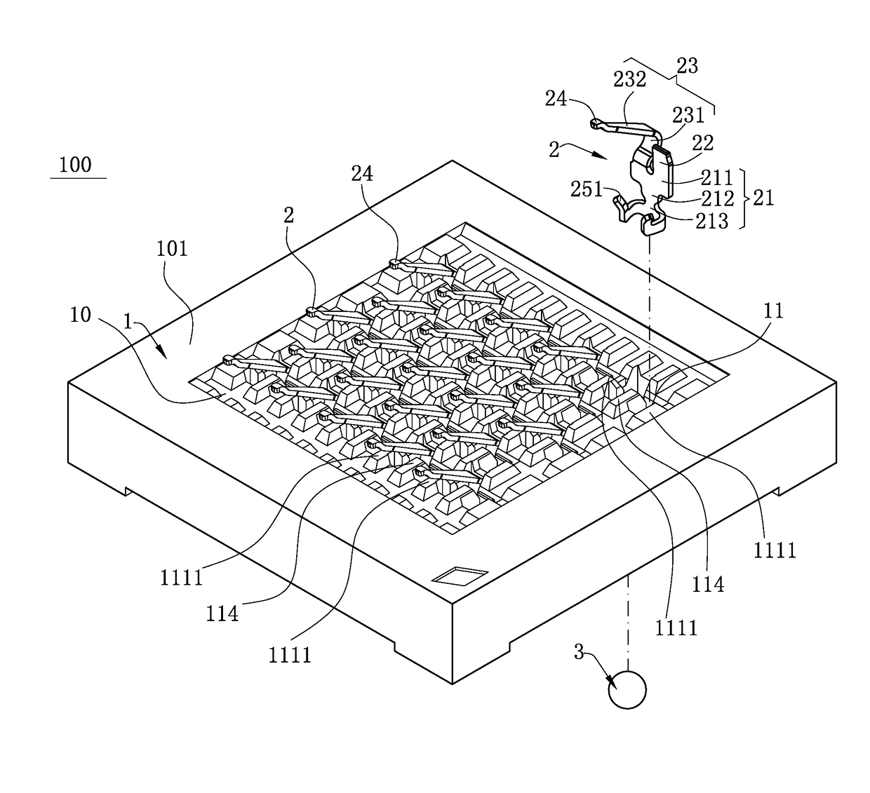
The present invention is an electrical connector that has a stable retention of terminals and is easier to manufacture using low power. Compared to related art, certain embodiments of the invention have several beneficial advantages. Firstly, the design ensures even distribution of retention forces, reduces assembly difficulty and improves yield of products. Secondly, the positioning of the tin ball prevents upward movement and simplifies the terminal structure, reducing assembly difficulty and improving market competitiveness of the products.

Problems solved by technology

The foregoing electrical connector provides a structure of fixing the tin balls by using the terminals, but in the actual production process, the material connecting portion at one side of each of the terminals is retained between the stopping block and the inner wall of each of the receiving slots, so that the overall retaining force of the terminals is uneven, and thus the terminals are easily turned over when being assembled to the receiving slots from top to bottom, and the production yield of the electrical connector is reduced.
In addition, the extending arm of each of the terminals is bent into a C-shaped structure to limit the upward location of the tin ball, thereby increasing the stamping molding difficulty of the terminals, and increasing the production cost of the electrical connector.
Therefore, a heretofore unaddressed need exists in the art to address the aforementioned deficiencies and inadequacies.

Method used


Image

  • Electrical connector
  • Electrical connector
  • Electrical connector

Examples


Embodiment Construction

[0026]The present invention is more particularly described in the following examples that are intended as illustrative only since numerous modifications and variations therein will be apparent to those skilled in the art. Various embodiments of the invention are now described in detail. Referring to the drawings, like numbers indicate like components throughout the views. As used in the description herein and throughout the claims that follow, the meaning of “a”, “an”, and “the” includes plural reference unless the context clearly dictates otherwise. Also, as used in the description herein and throughout the claims that follow, the meaning of “in” includes “in” and “on” unless the context clearly dictates otherwise. Moreover, titles or subtitles may be used in the specification for the convenience of a reader, which shall have no influence on the scope of the present invention.

[0027]It will be understood that when an element is referred to as being “on” another element, it can be di...


PUM


Abstract

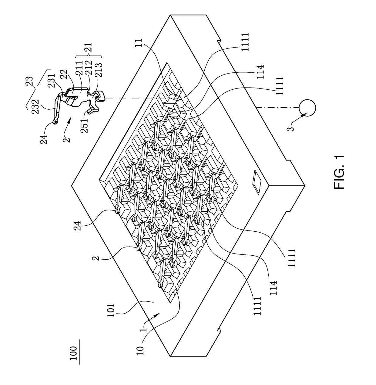
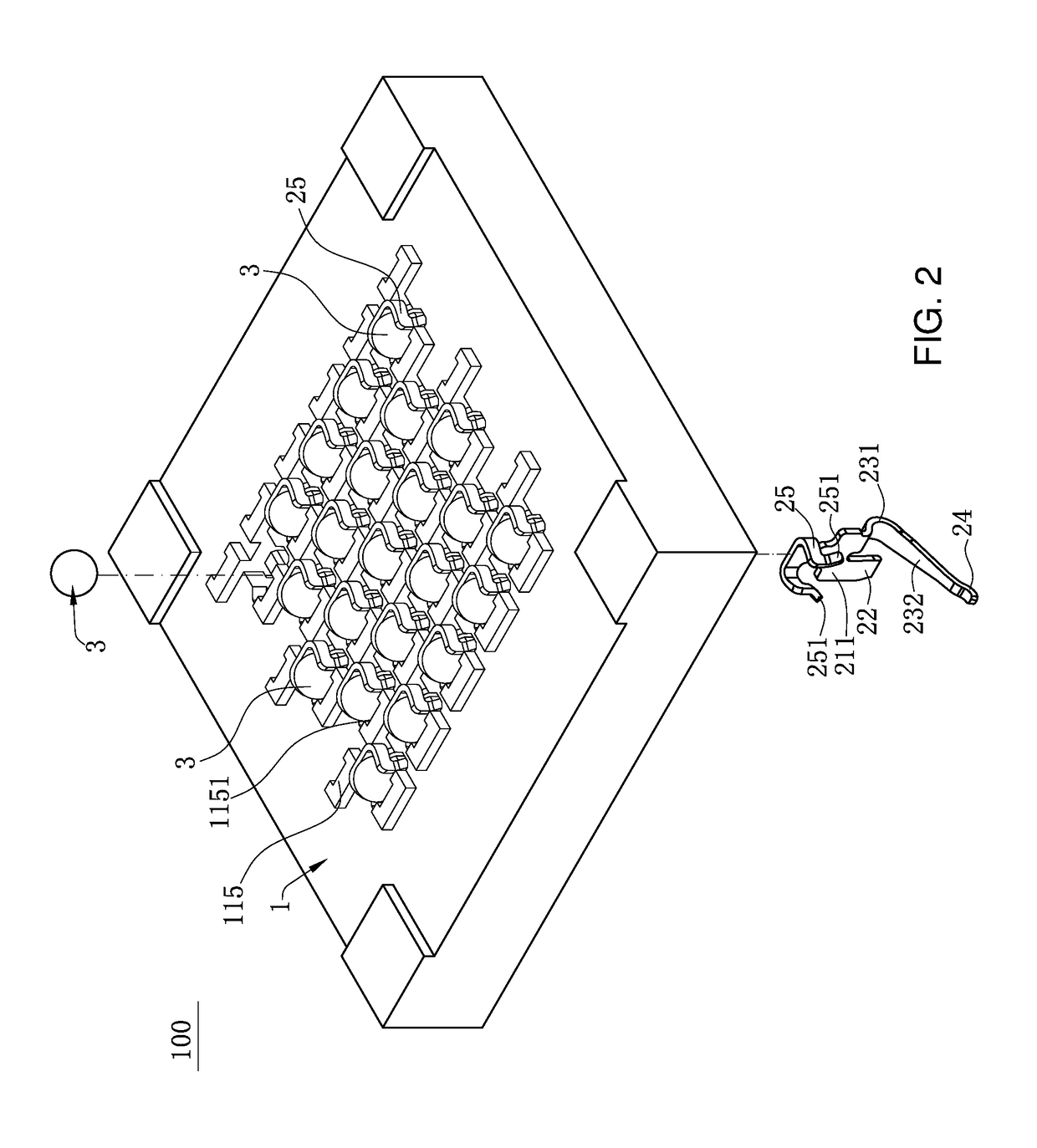
An electrical connector includes an insulating body having a bottom plate with receiving slots and multiple terminals received in the receiving slots. Each receiving slot has two opposite first side walls, and a second and third side walls connecting the first side walls. A protruding block protrudes from the second side wall toward the third side wall. Each terminal has a plate portion, an elastic arm and a material connecting portion extending upward from the plate portion, a contact portion at a top end of the elastic arm to urge a chip module, and two clamping portions bending and extending from two opposite sides of the plate portion horizontally. The plate portion and the material connecting portion are limited between the protruding block and the third side wall. Tin balls are fixed between the clamping portions, and soldered to a circuit board. The tin balls are below the protruding block.

Description

CROSS-REFERENCE TO RELATED APPLICATIONS[0001]This non-provisional application claims priority to and benefit of, under 35 U.S.C. §119(a), Patent Application No. 201621237863.1 filed in P.R. China on Nov. 18, 2016, the entire content of which is hereby incorporated by reference.FIELD OF THE INVENTION[0002]The present invention relates to an electrical connector, and more particularly to an electrical connector for electrically connecting a chip module to a circuit board.BACKGROUND OF THE INVENTION[0003]Chinese Patent Application No. CN201220644972.0 discloses an electrical connector for electrically connecting a chip module to a circuit board. The electrical connector includes an insulating body having multiple receiving slots and multiple terminals received in the receiving slots. The terminals conduct the chip module and are soldered to the circuit board. A stopping block is disposed in each of the receiving slots. Each of the terminals has a flat plate portion. One side of the pla...

Claims


Application Information

Patent Timeline
Patent Type & Authority Patents(United States)
IPC IPC(8): H01R12/00H01R12/58H01R13/24
CPCH01R12/585H01R13/2442H01R12/57H01R12/7076H01R12/714
Inventor JU, TED
Owner LOTES
Why Eureka
Eureka Blog
Learn More