
Method for controlling a piston cooling circuit of an internal combustion engine of an industrial vehicle

a technology of internal combustion engine and cooling circuit, which is applied in the direction of engine lubrication, engine cooling apparatus, mechanical apparatus, etc., can solve the problems of increasing the thermal load to be sustained by the engine, difficult to dissipate the heat generated, and requiring a certain energy expenditure to use oil spray nozzles, so as to achieve the effect of not losing any efficiency

Active Publication Date: 2017-10-31
FPT IND
View PDF28 Cites 2 Cited by
  • Summary
  • Abstract
  • Description
  • Claims
  • Application Information

AI Technical Summary

Benefits of technology

This approach reduces the energetic expenditure by about 50% and recovers energy typically lost during downward strokes, while maintaining effective cooling, resulting in improved engine efficiency and reduced emissions by optimizing oil flow and pressure utilization.

Problems solved by technology

In recent years, specific horsepower delivered by piston internal combustion engines has more and more increased, which has resulted inevitably in an increase of the thermal loads to be sustained by the engine.
The components that have to bear the highest stress in terms of thermal load are the pistons, since it is very difficult to dissipate the heat generated by the combustion.
It has been observed that using oil spray nozzles requires, however, a certain energetic expenditure.
Firstly the oil sprayed by the nozzles has to be pressurized by means of the oil circulation pump.
This, of course, determines a loss in terms of power.
Secondly, the heat removed from the oil increases its temperature and makes it necessary to cool the oil itself, usually by means of an oil-air or oil-water exchanger.
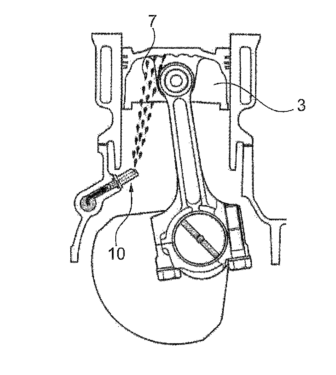
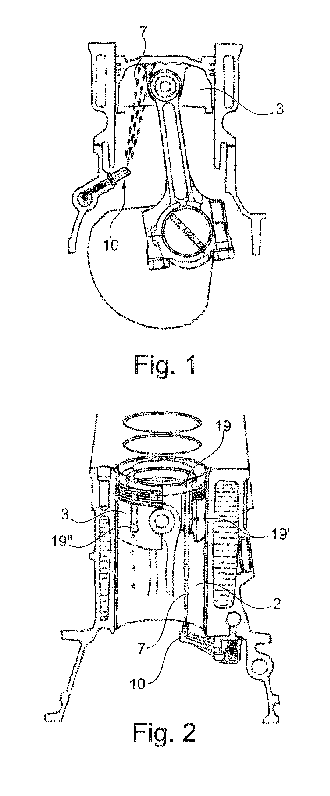
In practice, during the downward stroke, the losses for the oil pressurization add to the ones for the piston braking and this energy cannot be recuperated; during the upward stroke, from the BDC to the TDC, the energy spent by the oil pump in the form of thrust to the piston is partially recuperated.
It is thus evident that as such speed increases, the oil circulation pump would determine an excessive increase of the oil pressure.
It is evident, however, that the pressure release of the by-pass represents an energy, and thus a power, loss.
In particular, in conditions of low rpm and of low load, the electric valve keeps the nozzles closed.
Actually, during this step, the oil cannot exert even the possible thrust effect on the pistons during the upward stroke.
In practice, the cut-in / cut-off electric valve actually allows to save energy with low speeds of rotation, but in fact it is useless with high speeds of rotation or with higher loads.

Method used


Image

  • Method for controlling a piston cooling circuit of an internal combustion engine of an industrial vehicle
  • Method for controlling a piston cooling circuit of an internal combustion engine of an industrial vehicle
  • Method for controlling a piston cooling circuit of an internal combustion engine of an industrial vehicle

Examples


Embodiment Construction

[0025]The present invention thus refers to a method for controlling a piston cooling circuit of an internal combustion engine and to a cooling circuit where such method is applied. On this point, FIG. 3 shows a schematic view of a cooling circuit 1 according to the invention, intended, in particular, to cool the pistons of a diesel engine. The circuit according to the invention, however, may be used for the same purposes also in a gasoline engine.

[0026]The cooling circuit 1 comprises a circulation pump 4 for pumping oil from the sump 3 of the engine by means of a draft device 8 connected to the suction of the pump itself. In a first alternative embodiment, the pump 4 may be directly connected to the shaft of the combustion engine, so that the oil flow rate of the pump, and thus the delivery oil pressure depends directly on the speed of rotation of the drive shaft. In an alternative embodiment, the pump 4 may also be of the variable flow rate type. Compared to the previous one, such ...


PUM


Abstract

The present invention refers to a method for controlling a piston cooling circuit of an internal combustion engine wherein said circuit comprises at least a circulation pump and means for emitting cooling oil connected to the delivery of the pump. According to the method, said pistons are cooled by a jet generated by said emitting means only during the upward stroke of said pistons from the bottom dead center to the top dead center.

Description

CROSS REFERENCE TO RELATED APPLICATIONS[0001]The present application claims priority to PCT International Application No. PCT / EP2013 / 057981 filed on Apr. 17, 2013, which application claims priority to European Patent Priority No. 12164392.8 filed Apr. 17, 2012, the entirety of the disclosures of which are expressly incorporated herein by reference.STATEMENT RE: FEDERALLY SPONSORED RESEARCH / DEVELOPMENT[0002]Not Applicable.FIELD OF THE INVENTION[0003]The present invention belongs to the field of the manufacturing of internal combustion engine systems for vehicles, preferably industrial vehicles, commercial vehicles and / or trucks. More precisely the invention refers to a method for controlling a piston cooling circuit of an internal combustion engine, preferably, but not exclusively, of an industrial vehicle.DESCRIPTION OF THE PRIOR ART[0004]In recent years, specific horsepower delivered by piston internal combustion engines has more and more increased, which has resulted inevitably in...

Claims


Application Information

Patent Timeline
Patent Type & Authority Patents(United States)
IPC IPC(8): F01M1/08F01P3/06F01M1/14F01M1/02
CPCF01M1/08F01M1/02F01P3/06F01M1/14F01M2001/083
Inventor D'EPIRO, CLINO
Owner FPT IND
Learn More