
Light guide plate and surface illumination device

a surface illumination and light guide technology, applied in the direction of optical light guides, instruments, optics, etc., can solve the problems of reducing the light use efficiency of the light guide plate, and the improvement of so as to prevent the generation of bright lines, improve the light use efficiency of the surface illumination device, and increase the angle of incidence

Inactive Publication Date: 2017-10-24
ORMON CORP
View PDF2 Cites 5 Cited by
  • Summary
  • Abstract
  • Description
  • Claims
  • Application Information

AI Technical Summary

Benefits of technology

[0025]In particular, in one or more embodiments of the present invention, when viewed from above, both side surfaces of the light conducting portion are inclined relative to a direction orthogonal to the light conducting portion to increase the width of the light conducting portion in accordance with a distance from the light conducting portion.
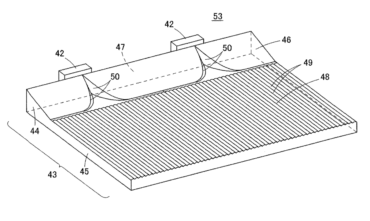
[0034]A light guide plate and surface illumination device according to one or more embodiments of the invention is provided with a groove formed by two cylindrical surfaces cut into a slanted surface. The slanted surface is configured such that an inclination between the slanted surface and a surface of a main light guiding body near the cylindrical surfaces is smaller than an inclination between an axis center of the cylindrical surfaces and the surface of the main light guiding body. Therefore, light reflected by the slanted surface, and in particular the light reflected by the cylindrical surfaces and the slanted surface have a larger angle of incidence when incident on the lower surface and the upper surface of the main light guiding body. Consequently, the light tends not to leak from the main light guiding body. As a result, the light use efficiency of a surface illumination device provided with a groove created between cylindrical surfaces improves, while preventing the generation of bright lines.

Problems solved by technology

Despite that, even if a planar light guide plate were given a thin profile, there are limitations to reducing the height of the LED in the light source.
In this manner when the light source protrudes from above than the light guide plate, a portion of the light emitted from the light source leaks externally without all the light entering the light input surface of the light guide plate, reducing the light use efficiency in the light guide plate.
However, as the demand increases for higher-quality surface illumination devices, even the improvements to the light use efficiency in the surface illumination device 11 illustrated in FIG. 1 become less adequate.
Consequently, it is not possible to obtain sufficient light use efficiency.
However, based on the above technical background, there is a need to prevent the reduction in light use efficiency and the generation of bright lines that occur when adding the lenticular lens.

Method used


Image

  • Light guide plate and surface illumination device
  • Light guide plate and surface illumination device
  • Light guide plate and surface illumination device

Examples


first embodiment

[0067]A surface illumination device 41 according to a first embodiment is described below with reference to FIGS. 7, 8A, and 8B. FIG. 7 is a perspective view of a surface illumination device 41 according to the first embodiment. FIG. 8A is a plan view of the surface illumination device 41; and FIG. 8B is a side view of the surface illumination device 41.

[0068]The surface illumination device 41 contains a light source 42, and a light guide plate 43. The light source 42 may have one or a plurality of LEDs installed that emit white light. Thereby, the light source 42 outputs light from a light output window in the front surface thereof.

[0069]The light guide plate 43 includes a thin, planar main light guiding body 45, and a light conducting portion 44. The light conducting portion 44 is provided continuing from an end of the main light guiding body 45. The light guide plate 43 may be integrally formed from a transparent resin having a high refractive index such as an acrylic resin, a po...

second embodiment

[0085]FIGS. 15A and 15B are respectively a perspective and a plan view illustrating a light guide plate 61 according to a second embodiment. FIG. 16A is a cross-sectional view along the line X-X in FIG. 15B. Both side surfaces of the light conducting portion 44 are cut diagonally in the light guide plate 61 according to the second embodiment. The surfaces that are cut diagonally become light reflecting walls 62. Note that other portions of the structure are identical to the light guide plate in the first embodiment. Therefore the portions identical to those in the first embodiment are given the same reference numerals, and further explanation thereof is omitted.

[0086]In the light guide plate 61, the light is reflected transversely by the cylindrical surfaces 50, and repeatedly reflected on the upper and lower surfaces of the light conducting portion 44 until reaching the side surfaces of the light conducting portion 44. This light is subsequently reflects on the light reflecting wal...

third embodiment

[0094]FIG. 21A is a perspective view illustrating a surface illumination device 71 according to a third embodiment; and FIG. 21B is a plan view of the surface illumination device 71. The surface illumination device 71 is provided with a directivity conversion pattern 72 in a region between the slanted surface 46 and the lenticular lens 49.

[0095]As illustrated in FIGS. 21A and 21B, the directivity conversion pattern 72 is a plurality pattern elements 73 arranged as V-grooves along the radiation direction. That is, when viewed from a direction orthogonal to the light output surface 48, each of the pattern elements 73 pass through the light emission center of the light source 42, and is inclined relative to an imaginary straight line perpendicular to the light input surface 47 (referred to below as an optical axis K of the light source 42). Further, each of the pattern elements 73 on either side of the optical axis K is inclined in the opposite direction. Moreover, the angle each of th...


PUM

PropertyMeasurementUnit
widthaaaaaaaaaa
widthaaaaaaaaaa
widthaaaaaaaaaa

Abstract

A light guide plate has a light conducting portion having a light input surface for introducing light into the light guide plate, a main light guiding body that is thinner than a maximum thickness of the light conducting portion, and disposed continuously from the light conducting portion, a slanted surface that is disposed on the light conducting portion on at least one of a surface near a light output surface and a surface opposite the surface near the light output surface, and that is inclined from a section of the light guide plate that is thicker than the main light guiding body toward an end of the main light guiding body, two cylindrical surfaces that cut into the slanted surface, and a groove formed by the two cylindrical surfaces.

Description

BACKGROUND[0001]Field[0002]The present invention relates to a light guide plate and a surface illumination device. More specifically the present invention relates to a surface illumination device used as a backlight in a liquid crystal display device, and a light guide plate used in said surface illumination device.[0003]Related Art[0004]As mobile devices with built-in surface illumination devices become thinner, the surface illumination devices are required to have increasingly thinner profiles. Consequently, the light guide plate must also have a thinner profile to create a thinner surface illumination device. Despite that, even if a planar light guide plate were given a thin profile, there are limitations to reducing the height of the LED in the light source. Therefore, when using a planar light guide plate, the height of the light source will be greater than the thickness of an end surface (light input surface) of the light guide plate. Thus, the light source, which is arranged ...

Claims


Application Information

Patent Timeline
Patent Type & Authority Patents(United States)
IPC IPC(8): F21V8/00G02F1/1335
CPCG02B6/0018G02B6/002G02B6/005G02B6/0058G02F1/133602G02F1/133615G02F1/133524G02B6/0038G02B6/0028
Inventor SHINOHARA, MASAYUKIKITAMURA, NORIKAZUHIROTA, KAZUHIDE
Owner ORMON CORP
Learn More