
Spectrophotometer

a spectrophotometer and wavelength correctness technology, applied in the field of spectrophotometers, can solve the problems of data size increase and accuracy of wavelength correctness, and achieve the effect of accurately performing validation of wavelength correctness

Active Publication Date: 2017-10-10
SHIMADZU CORP
View PDF8 Cites 0 Cited by
  • Summary
  • Abstract
  • Description
  • Claims
  • Application Information

AI Technical Summary

Benefits of technology

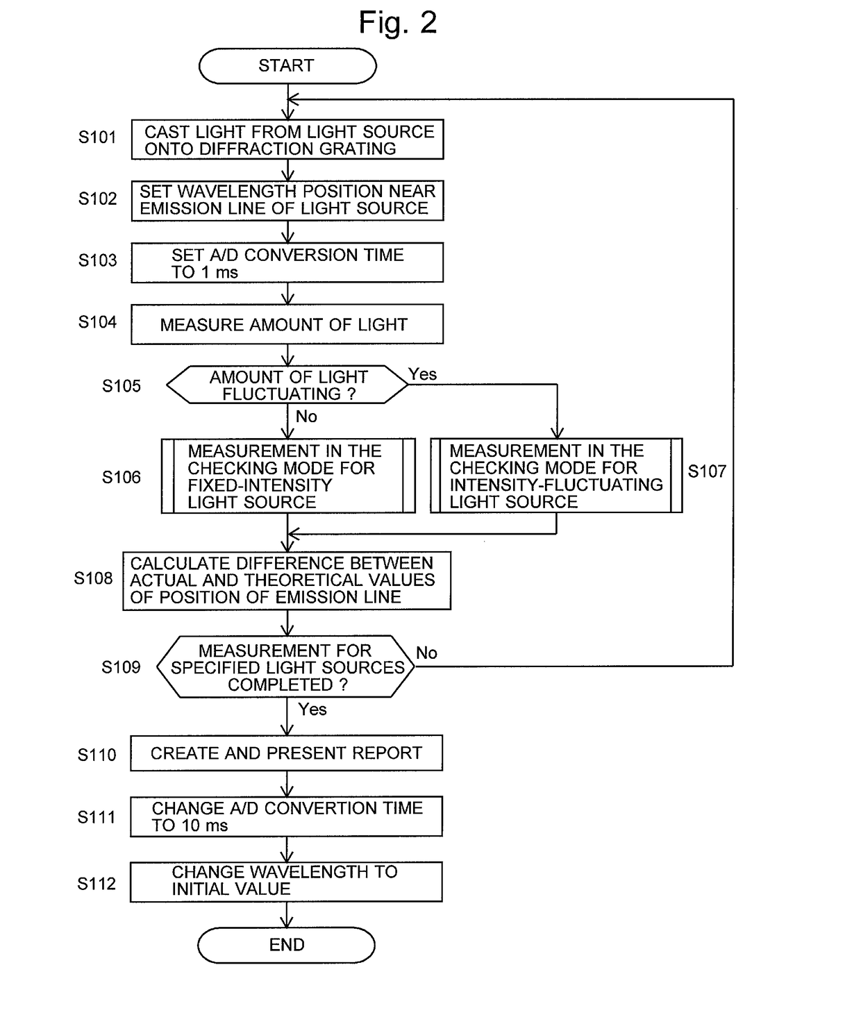
[0042]As described thus far, in the spectrophotometer according to any of the previously described aspects of the present invention, the A / D converter has a variable A / D conversion time, which can be varied through the A / D conversion time controller according to the operation mode of the spectrophotometer (sample measurement mode or wavelength-correctness validation mode), according to whether or not there is a fluctuation of the amount of light emitted from the light source, or according to the kind of light source to be used for the casting of the measurement light. With this system, for example, even when a low-pressure mercury lamp or similar AC-energized light source is used, the influence from the temporal fluctuation of the emission intensity of the light source can be eliminated by increasing the A / D conversion time in the A / D converter and thereby accumulating the signals from the photodetector to a sufficient amount, so that the validation of the wavelength correctness can be accurately performed.

Problems solved by technology

However, a problem exists in that the data size increases.
This error represents the accuracy of the “wavelength correctness” in the light separator.

Method used


Image

  • Spectrophotometer
  • Spectrophotometer
  • Spectrophotometer

Examples


Embodiment Construction

[0052]One mode for carrying out the present invention is hereinafter described, giving one embodiment.

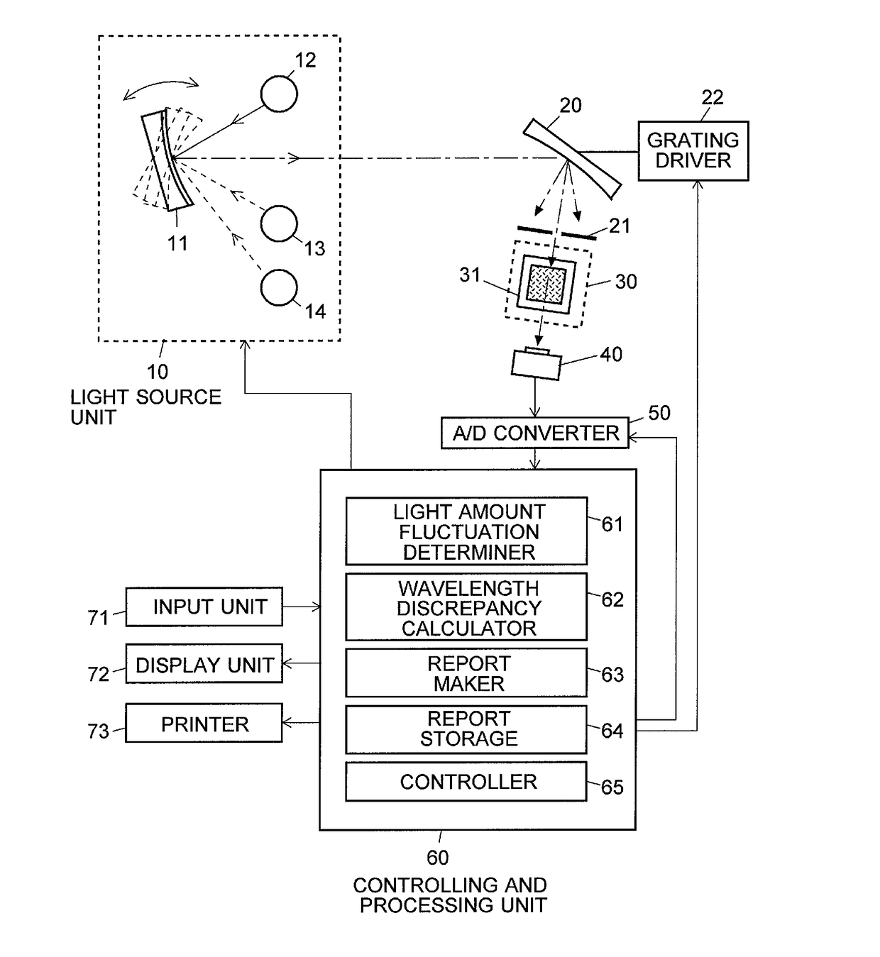
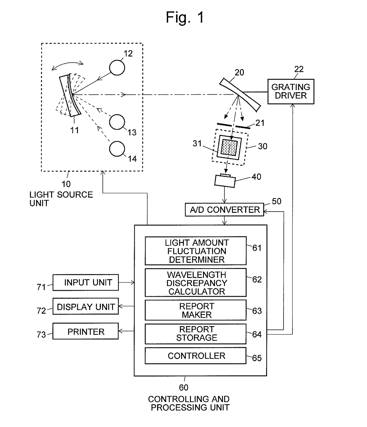
[0053]FIG. 1 shows a schematic configuration of the spectrophotometer according to the present embodiment. A light-source unit 10 selectively allows light emitted from one of a xenon lamp 12, a deuterium lamp 13 and a low-pressure mercury lamp 14 to be cast onto a diffraction grating 20 by rotating a light-source selecting mirror 11. The light introduced to the diffraction grating 20 is separated into wavelength components by the grating 20. A component of light having a specific wavelength is extracted from the wavelength-dispersed light by a slit 21 and cast onto a sample cell 31 contained in a sample container 30. The intensity (amount) of light which has passed through the sample cell 31 and the sample solution contained in the cell 31 is detected with a photodetector 40, such as a photodiode, and the obtained current signal is sent to an A / D converter 50. The A / D converter 50 i...


PUM


Abstract

Provided is a spectrophotometer having a sample container 30, a light-source unit 10 for casting measurement light into the sample container 30, a photodetector 40 for detecting light obtained from the sample container 30 illuminated with the measurement light, a light separator 20 placed between the light-source unit 10 and the sample container 30, an A / D converter 50 for converting detection signals from the photodetector 40 into digital signals, and an A / D conversion time controller 65 for controlling an A / D conversion time in the A / D converter 50. The A / D converter 50 receives, for each A / D conversion time, detection signals sequentially produced by the photodetector 40, and sequentially outputs values corresponding to the amounts of signals received. The A / D conversion time controller 65 controls the A / D conversion time at five times (preferably, ten times) the cycle of commercial power supplies or longer during wavelength-correctness validation of the light separator 20.

Description

TECHNICAL FIELD[0001]The present invention relates to a spectrophotometer.BACKGROUND ART[0002]In general, in a spectrophotometer, monochromatic light having a specific wavelength is extracted by introducing light emitted from a light source into a light separator, and this monochromatic light is cast onto or into a sample as measurement light. The wavelength of the light which interacts with the sample is specific to the substances contained in the sample. Accordingly, detecting the light after the interaction (e.g. transmitted, reflected, scattered or fluorescent light) with a photodetector enables quantitative and / or qualitative determination of the sample based on the detection signal, the wavelength of the cast light and other information.[0003]For example, in a measurement of a sample using an ultraviolet-visible spectrophotometer, light emitted from a light source having a continuous spectrum over a comparatively broad range of wavelengths, such as a halogen lamp or deuterium ...

Claims


Application Information

Patent Timeline
Patent Type & Authority Patents(United States)
IPC IPC(8): G01J3/42G01J3/28G01J3/18G01J3/10G01J3/02
CPCG01J3/10G01J3/027G01J3/28G01J3/2803G01J3/18G01J2003/102
Inventor BUNGO, HAJIME
Owner SHIMADZU CORP
Learn More