
Rocket motors having controlled autoignition propellant systems

Active Publication Date: 2017-10-10
AEROJET ROCKETDYNE INC
View PDF12 Cites 1 Cited by
  • Summary
  • Abstract
  • Description
  • Claims
  • Application Information

AI Technical Summary

Benefits of technology

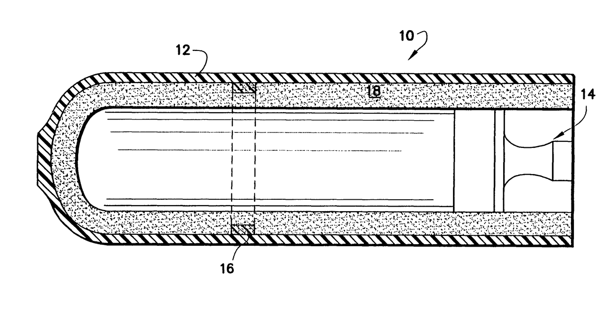
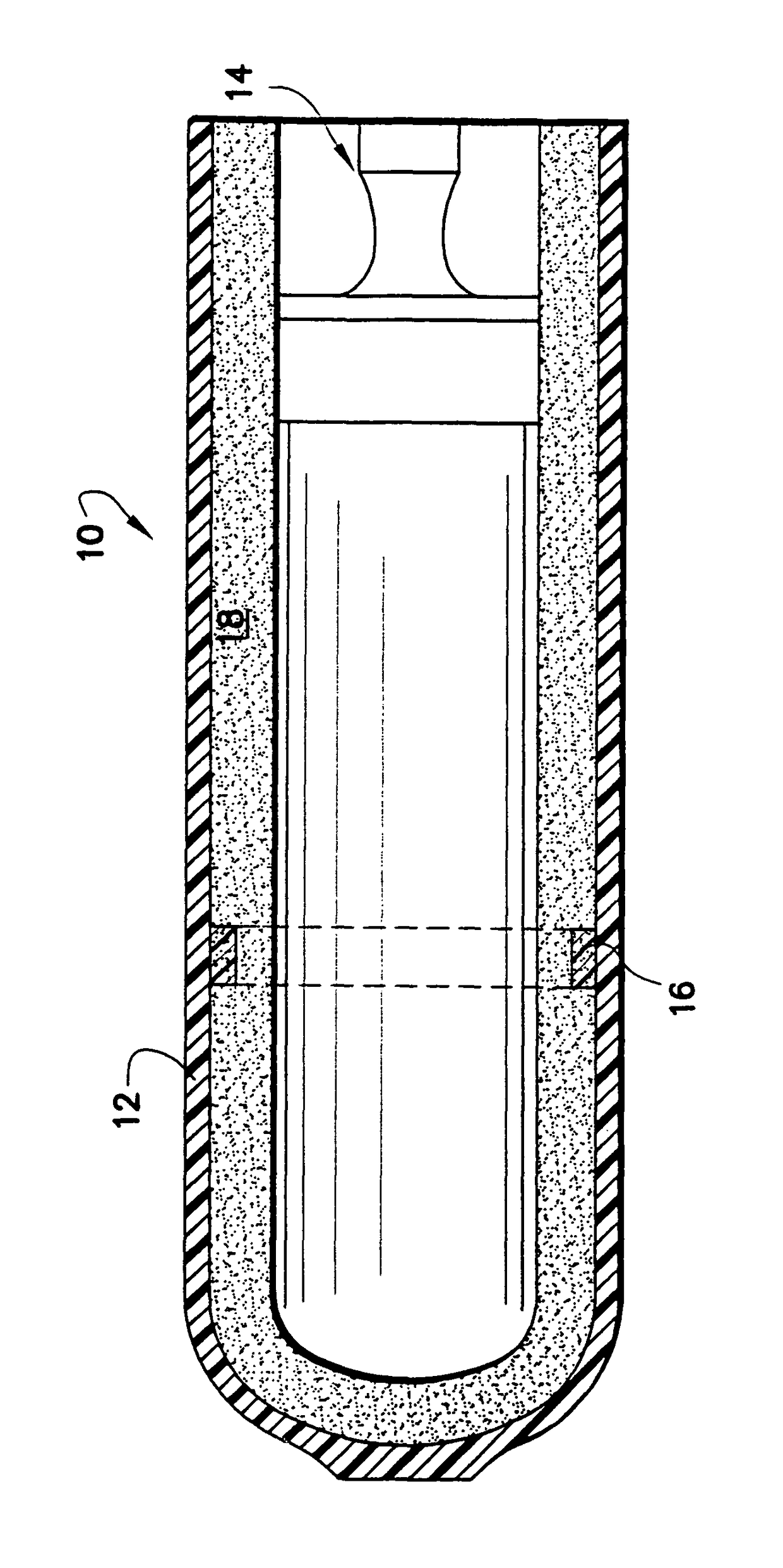
The patent describes a method to reduce the risk of reaction violence in a rocket motor by using a secondary propellant that is in physical contact with a localized region of the main propellant near the motor casing. This helps to create a critical mass that allows for reduced heat generation and minimizes decomposition of the main propellant when the secondary propellant autoignites. The technical effect is safer and more reliable operation of the rocket motor.

Problems solved by technology

When autoignition finally occurs, around 450° F., the high surface area of the porous propellant causes rapid overpressurization in the rocket motor leading to destruction.

Method used


Image

  • Rocket motors having controlled autoignition propellant systems
  • Rocket motors having controlled autoignition propellant systems

Examples


example 2 (

Invention)

[0016]Example 1 was repeated except that a 1-inch wide x. 0.1 inch thick mitigation strip of AFX-960 (HMX, nitroguanidine and HTPB) was placed between the motor case and the high-energy propellant. In the slow cook-off testing that ensued, the test item reacted at 35.7 hours after the test was begun and at a temperature of 297° F., yielding a burning-only type of reaction. The oven was opened and most of the metal test hardware was reusable. The case split into two major parts at the location of the mitigation strip.

example 3 (

Invention)

[0017]Example 2 was repeated except that GAP-960 (HMX, nitroguanidine and GAP binder) was employed for the mitigation strip. Identical results to those obtained in Example 2 were obtained.


PUM


Abstract

Solid propellant systems include a main propellant and a secondary propellant in contact with the first propellant that exhibits autoignition temperatures of at least about 100° F. lower than the autoignition temperature of the main propellant. The secondary propellant of the present invention is most advantageously employed with conventional AP-containing solid propellant formulations as the main propellant, especially formulations containing both AP, an energetic solid, and a binder. In especially preferred forms, the secondary propellant will include a nitramine which is at least one selected from nitroguanidine (NQ), cyclotrimethylene trinitramine (RDX) and cyclotetramethylenetetranitramine (HMX), and a binder which is at least one selected from HTPB, HTPE or glycidyl azide polymer (GAP). Most preferably, the secondary propellant will include a combination of nitramines which includes NQ and one of RDX or HMX.

Description

FIELD OF THE INVENTION[0001]The present invention relates generally to solid propellants usefully employed in rocket motors. In especially preferred forms, the present invention is related to propellant systems having controlled autoignition characteristics.BACKGROUND AND SUMMARY OF THE INVENTION[0002]Typical solid propellants for rocket motors contain ammonium perchlorate (AP) and sometimes aluminum powder in a rubbery matrix, typically of hydroxyl-terminated polybutadiene (HTPB). The autoignition temperature of these propellants is controlled by the decomposition of ammonium perchlorate and the interactions of the decomposition products with the rubbery binder, that lead to porosity in the propellant grain. When autoignition finally occurs, around 450° F., the high surface area of the porous propellant causes rapid overpressurization in the rocket motor leading to destruction.[0003]Conventional techniques to control autoignition of solid rocket motor propellants has included depos...

Claims


Application Information

Patent Timeline
IPC IPC(8): F02K9/28C06B45/10F02K9/95F02K9/12C06B45/12C06B25/34C06B29/22F42B15/00F42C15/36C06B45/34
CPCF42B15/00F42C15/36F02K9/12C06B45/12C06B45/34C06B29/22F02K9/95F02K9/28C06B45/10C06B25/34F42B39/20
Inventor GRAHAM, KENNETH J.GROVE, EDNA M.LYNCH, ROBERT D.SPEAR, GUY B.
Owner AEROJET ROCKETDYNE INC
Learn More