
Magnetic tape and magnetic tape device

a magnetic tape and magnetic tape technology, applied in the field of magnetic tape and magnetic tape devices, can solve the problems of more errors during recording and/or reproduction, difficult for the magnetic head to accurately follow the data track, etc., and achieve the effect of enhancing electromagnetic characteristics, and increasing the surface smoothness of the magnetic layer

Active Publication Date: 2017-10-03
FUJIFILM CORP
View PDF5 Cites 111 Cited by
  • Summary
  • Abstract
  • Description
  • Claims
  • Application Information

AI Technical Summary

Benefits of technology

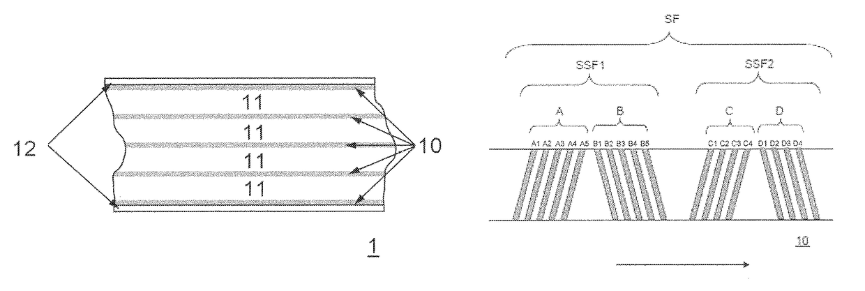
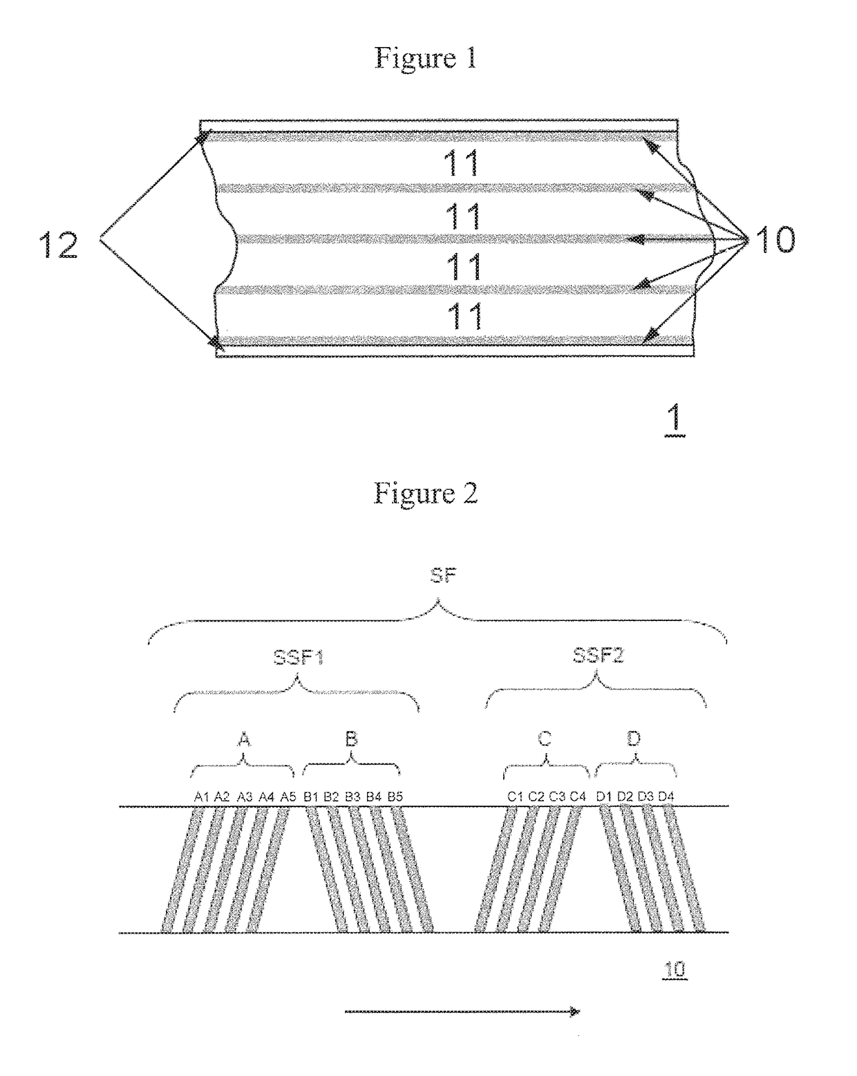
The present invention provides a magnetic tape with a timing based servo pattern that has a smooth surface and high precision of head positioning. This results in the accurate recording and reproducing of magnetic signals on the tape. The invention also provides a magnetic tape device for recording and playing back magnetic signals on this tape.

Problems solved by technology

However, when the data track width is reduced, in the process of running a magnetic tape within a magnetic tape device (commonly called a “drive”) for recording and / or reproducing a magnetic signal, variation in the position of the magnetic tape in the widthwise direction makes it difficult for the magnetic head to accurately follow the data track.
This tends to cause more errors to occur during recording and / or reproduction.

Method used


Image

  • Magnetic tape and magnetic tape device
  • Magnetic tape and magnetic tape device

Examples


example 1

[0132]The formula of each of the layer-forming compositions is set forth below.

(Magnetic Layer-Forming Composition)

(Magnetic Liquid)

[0133]Ferromagnetic hexagonal barium ferrite powder 100.0 parts[0134]Ferromagnetic hexagonal barium ferrite powder (1) (average particle size (average plate diameter) and formula ratio: See Table 1)[0135]Ferromagnetic hexagonal barium ferrite powder (2) (average particle size (average plate diameter) and formula ratio: See Table 1)

[0136]Oleic acid: 2.0 parts

[0137]Vinyl chloride copolymer (MR-104 made by Zeon Corp.): 10.0 parts

[0138]SO3Na group-containing polyurethane resin: 4.0 parts[0139](weight average molecular weight: 70,000, SO3Na groups: 0.07 meq / g)

[0140]Methyl ethyl ketone: 150.0 parts

[0141]Cyclohexanone: 150.0 parts

(Abrasive Liquid)

[0142]α-Alumina (BET specific surface area: 19 m2 / g): 6.0 parts

[0143]SO3Na group-containing polyurethane resin[0144](weight average molecular weight: 70,000, SO3Na groups: 0.1 meq / g): 0.6 part

[0145]2,3-Dihydroxynaphth...

examples 2 to 6

, Comparative Examples 1 to 5

[0206]With the exceptions that the formula of the magnetic layer-forming composition shown in Table 1 and / or the manufacturing conditions were changed, magnetic tapes were fabricated by the same methods as in Example 1.

[0207]The formula ratio of the ferromagnetic hexagonal barium ferrite powder given in Table 1 refers to the content by weight of the various ferromagnetic hexagonal barium ferrite powders relative to 100.0 weight parts of the total quantity of ferromagnetic powder. The average particle size of the ferromagnetic hexagonal barium ferrite powder given in Table 1 is a value obtained by collecting a necessary quantity from a powder lot used to fabricate magnetic tape and measuring the average particle size by the method described above. Following measurement, the ferromagnetic hexagonal barium ferrite powder was used to prepare the magnetic liquid for fabricating magnetic tape.

[0208][Evaluation Methods]

(1) Magnetic Layer Surface Ra

[0209]An atom...


PUM

PropertyMeasurementUnit
surface roughness Raaaaaaaaaaa

Abstract

The magnetic tape has a magnetic layer containing ferromagnetic powder and binder on a nonmagnetic support, wherein a timing based servo pattern is present on the magnetic layer, the centerline average surface roughness Ra that is measured on the surface of the magnetic layer is less than or equal to 1.8 nm, and the coefficient of friction that is measured on the base portion of the surface of the magnetic layer is less than or equal to 0.35.

Description

CROSS-REFERENCE TO RELATED APPLICATIONS[0001]This application claims priority under 35 U.S.C 119 to Japanese Patent Application No. 2016-056850 filed on Mar. 22, 2016. The above application is hereby expressly incorporated by reference, in its entirety.BACKGROUND OF THE INVENTION[0002]Field of the Invention[0003]The present invention relates to a magnetic tape and a magnetic tape device.[0004]Discussion of the Background[0005]Magnetic recording media include tape-shaped media and disk-shaped media. Magnetic recording media in the form of tapes—that is, magnetic tapes—are primarily employed in data storage applications such as data backup and archives. Information is typically recorded on a magnetic tape by recording a magnetic signal on the data band of the magnetic tape. Thus, data tracks are formed on the data band.[0006]In recent years, the steep rise in the overall quantity of information in existence has been accompanied by increased demand for magnetic tapes capable of higher ...

Claims


Application Information

Patent Timeline
Patent Type & Authority Patents(United States)
IPC IPC(8): G11B5/78G11B5/712G11B5/592
CPCG11B5/712G11B5/5926G11B5/78G11B5/70
Inventor KASADA, NORIHITOKANEKO, TETSUYAOZAWA, EIKI
Owner FUJIFILM CORP
Learn More