Reducing friction of a viscous fluid flow in a conduit

a technology of viscous fluid and friction reduction, which is applied in the direction of pipeline systems, thin material handling, gas/liquid distribution and storage, etc., can solve the problems of unacceptably high capital cost of pumping equipment and operating energy cost, uneven film distribution about the viscous flow, etc., to reduce the pressure variation, reduce the friction of the viscous fluid flow, the effect of reducing the pressure variation

Active Publication Date: 2017-09-12
COMMONWEALTH SCI & IND RES ORG
View PDF30 Cites 0 Cited by
  • Summary
  • Abstract
  • Description
  • Claims
  • Application Information

AI Technical Summary

Benefits of technology

[0014]wherein said fluid outlet arrangement comprises a substantially continuous opening or ring of close spaced openings about the flow path, and said cavity comprises an array of passages in said body that includes a plurality of elongate passages that extend about said flow path effective collectively to reduce the pressure variation and therefore velocity variation of the delivered lubricating fluid along said outlet arrangement.
[0015]The invention further provides a method of reducing friction of a viscous fluid flow in a conduit, comprising delivering lubricating fluid to the flow from a cavity via an outlet arrangement, wherein said fluid outlet arrangement comprises a substantially continuous opening or ring of close spaced openings about the flow, and said cavity comprises an array of passages in said body that includes a plurality of elongate passages that extend about said flow effective collectively to reduce the pressure variation and therefore velocity variation of the delivered lubricating fluid along said outlet arrangement.
[0022]Means, for example, suitable through-holes in the flanges and matching bolts, are provided for clamping the flanges together, and a circumferential seal is provided to prevent escape of lubricating fluid from the cavity.

Problems solved by technology

The benefits however come with a cost since the increased friction loss arising with increasing viscosity elevates pressures and power requirements for conveying viscous materials.
Sometimes the pressure required is so high that the capital cost for pumping equipment and the operating energy cost become unacceptably high.
Tests have shown that the delivery of the lubricating fluid from the circumferential slit is significantly non-uniform resulting in uneven film distribution about the viscous flow and a circumferentially variable downstream effect of the lubrication.
In typical systems employing water as the lubricating fluid, the resulting proportionate total addition of water, especially where a number of devices are provided over a longer pipeline, may be unacceptable and detrimental to the process, or simply so high as to offset the potential advantages of employing the thickened slurry or viscous fluid as a means of transport.

Method used


Image

  • Reducing friction of a viscous fluid flow in a conduit
  • Reducing friction of a viscous fluid flow in a conduit
  • Reducing friction of a viscous fluid flow in a conduit

Examples


Embodiment Construction

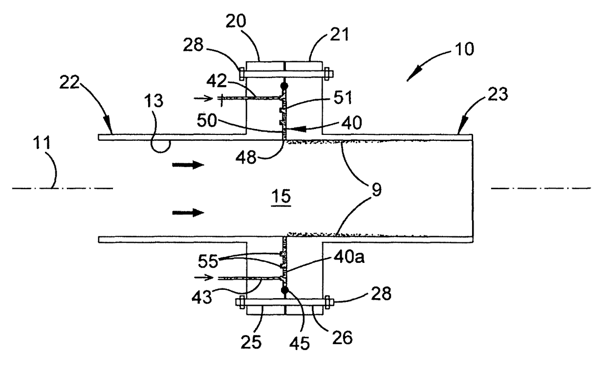
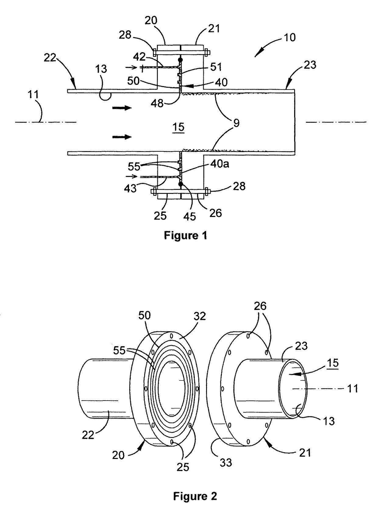
[0036]The device 10 illustrated in FIGS. 1 and 2 is intended to be installed as a segment of a conduit for flow of viscous fluid, for example a slurry paste in a mineral processing plant. Coupling arrangements at each end of the device are not illustrated as they would vary according to the application but typically there may be respective flanges by which the device might be clamped to complementary flanges of further conduit segments or to the outlets or intakes of pumping equipment or processing units.

[0037]The device 10 thus constitutes a body positionable to define at least a segment of a flow path 15 for viscous fluid in a conduit. The device may provide the whole conduit or more typically a section of the conduit. This body is formed by a pair of solid annular flanges 20, 21 each contiguous with a respective cylindrical conduit section 22, 23. The flanges have respective rings of complementary through-holes 25, 26 adjacent their outer peripheries for receiving, respective bol...


PUM


Abstract

A device for reducing friction of a viscous fluid flow in a conduit is disclosed. The device comprises a body positionable to define at least a segment of a flow path for the viscous fluid in or contiguous with the conduit, a cavity in the body for retaining lubricating fluid, and at least one port in the body for delivering lubricating fluid to the cavity. A fluid outlet arrangement from said cavity delivers lubricating fluid to the flow path to form a downstream lubricating film at the conduit surface. The fluid outlet arrangement comprises a substantially continuous opening or ring of close spaced openings, effective collectively to reduce the pressure variation and therefore velocity variation of the delivered lubricating fluid along said outlet arrangement.

Description

CROSS-REFERENCE TO RELATED APPLICATIONS[0001]This application is a §371 national stage of PCT International Application No. PCT / AU2013 / 000109, filed Feb. 7, 2013, claiming priority of Australian Patent Application No. 2012900442, filed Feb. 7, 2012, the contents of each of which are hereby incorporated by reference in their entirety.FIELD OF THE INVENTION[0002]This invention relates generally to the reduction of friction of a viscous fluid flow in a conduit by injection of a lubricating fluid between the viscous fluid and the wall of the conduit. The invention has particular application to the conveyance of thickened slurries in mining and mineral processing plants, but is also applicable in the transport of highly viscous fluids in a variety of other industries for example, the oil, cement, polymer, food and pharmaceutical industries.BACKGROUND OF THE INVENTION[0003]Thickened slurries are favoured for the transport of particulate solid streams in mining and mineral processing. Bene...

Claims


Application Information

Patent Timeline
Patent Type & Authority Patents(United States)
IPC IPC(8): F17D1/17F15D1/06F15D1/00F17D1/16
CPCF17D1/17F15D1/008F15D1/06F17D1/16Y10T137/0391Y10T137/2076Y10T137/2082
Inventor WU, JIEGRAHAM, LACHLANSHORT, GREGORY MARKHARRIS, DEAN WILLIAM
Owner COMMONWEALTH SCI & IND RES ORG
Why Eureka
Try Eureka