
Lighting control system and method for communication of short messaging

a control system and light control technology, applied in lighting devices, lighting sources, electrical devices, etc., can solve the problems of bulky controls, power line control is susceptible to influence, and cost problems for retrofitting, and achieve the effect of convenient trouble shooting and convenient commissioning

Active Publication Date: 2017-09-05
DOUGLAS LIGHTING CONTROLS
View PDF11 Cites 0 Cited by
  • Summary
  • Abstract
  • Description
  • Claims
  • Application Information

AI Technical Summary

Benefits of technology

The system and method described in this patent can be inexpensive and easy to set up and troubleshoot. Additionally, the system uses occupancy sensors that transmit signals in a way that reduces collisions with other wireless signals. The use of a low duty cycle transmission also allows for higher output power and longer range than continuous data systems.

Problems solved by technology

This poses a cost problem for retrofits where the control wires are not already in place.
While the cost is relatively less, the same problem exists in new construction where the wires must be procured and routed.
Power line control is susceptible to influence from noise and, in some implementations, requires bulky controls.
Wireless lighting controls have been employed on a limited basis, and typically use bi-directional messaging on relatively expensive platforms.
While these systems are powerful in their ability to transmit a significant amount of data, the devices employed are expensive; the software development is often significant; and system commissioning and troubleshooting are complex.
However, continuous data wireless bands are limited in their output power compared to unlicensed wireless bands targeted for spurious data transmission with very low duty cycle (400 MHz).
Further, many of the available wireless technologies are problematic in that they require significant research and development to implement them, they require skills typically unfamiliar to individuals installing lighting systems (e.g., network technology), and / or they are often difficult to troubleshoot (e.g., determine which device is failing).

Method used


Image

  • Lighting control system and method for communication of short messaging
  • Lighting control system and method for communication of short messaging
  • Lighting control system and method for communication of short messaging

Examples


Embodiment Construction

[0025]Throughout the specification and claims, the following terms take at least the meanings explicitly associated herein, unless the context dictates otherwise. The meanings identified below do not necessarily limit the terms, but merely provide illustrative examples for the terms. The meaning of “a,”“an,” and “the” may include plural references, and the meaning of “in” may include “in” and “on.” The phrase “in one embodiment,” as used herein does not necessarily refer to the same embodiment, although it may.

[0026]The term “coupled” means at least either a direct electrical connection between the connected items or an indirect connection through one or more passive or active intermediary devices.

[0027]The term “circuit” means at least either a single component or a multiplicity of components, either active and / or passive, that are coupled together to provide a desired function. Terms such as “wire,”“wiring,”“line,”“signal,”“conductor,” and “bus” may be used to refer to any known s...


PUM


Abstract

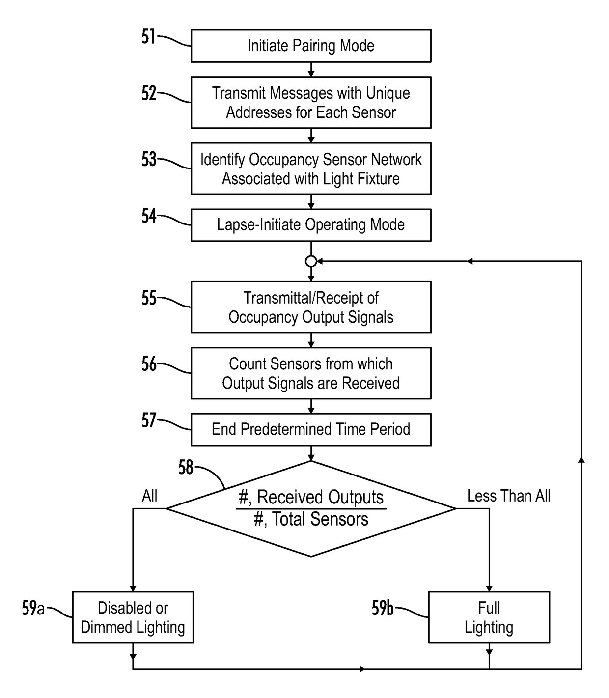
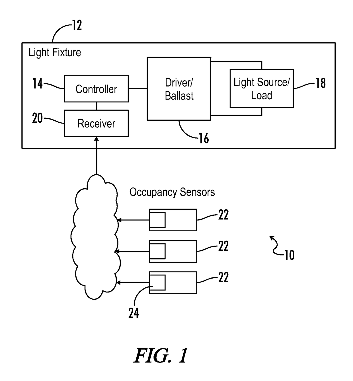
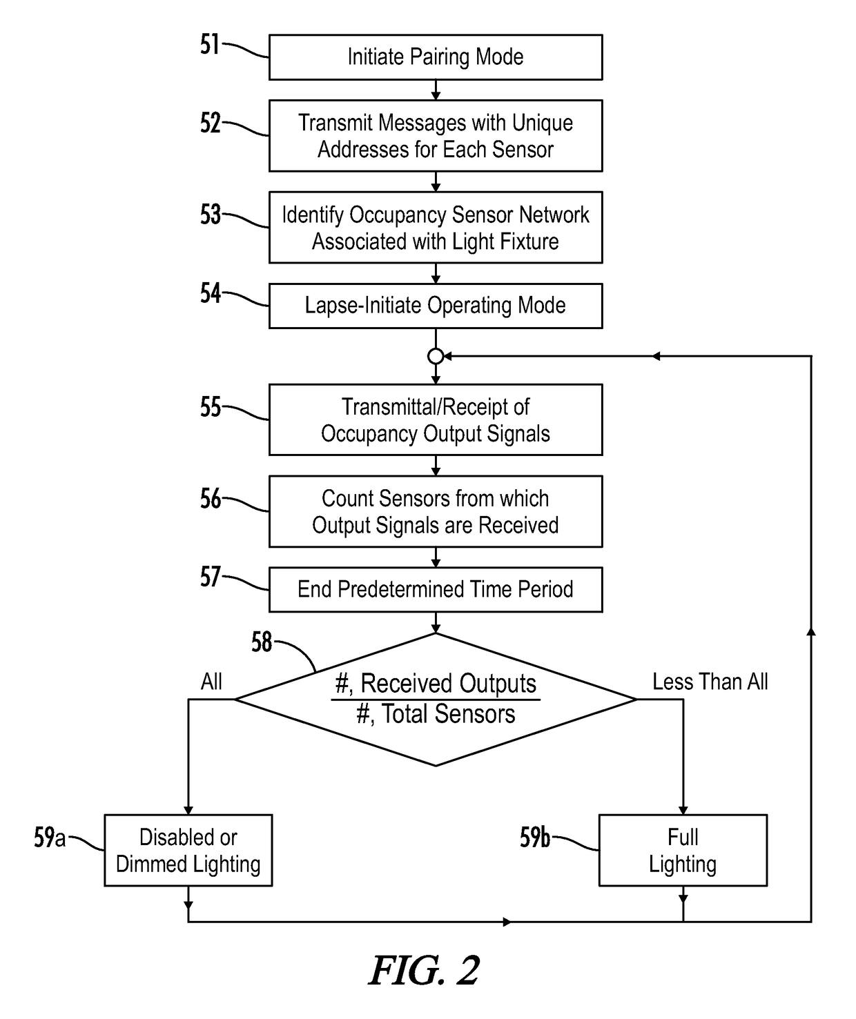
An area lighting control system is provided for a light fixture and occupancy sensors. In a pairing mode, the occupancy sensors transmit messages with respective unique addresses to the light fixture, which identifies an associated sensor network. Upon lapsing of the pairing mode, an operating mode follows during which the sensors transmit output signals representative of occupancy in the area, and the light fixture regulates respective light sources based on an occupancy state determined according to output signals received from the associated network. The output signals are transmitted according to pseudo-random time intervals in order to reduce wireless transmission collisions, and only upon determining no occupancy in the defined area. When signals are received from all sensors in the network during a predetermined time period, the light fixture dims the light sources, whereas otherwise the light fixture operates the light sources at full lighting state.

Description

[0001]A portion of the invention of this patent document contains material that is subject to copyright protection. The copyright owner has no objection to the reproduction of the patent document or the patent invention, as it appears in the U.S. Patent and Trademark Office patent file or records, but otherwise reserves all copyright rights whatsoever.CROSS-REFERENCES TO RELATED APPLICATIONS[0002]This application claims benefit of U.S. Provisional Patent Application No. 61 / 875,193, filed Sep. 9, 2013, and which is hereby incorporated by reference.BACKGROUND OF THE INVENTION[0003]The present invention relates generally to lighting control systems. More particularly, the present invention relates to a lighting control method wherein a light fixture identifies output signals from an associated occupancy sensor network and regulates a lighting state based on determined occupancy in a defined area.[0004]Due to the improvements in LED lighting technology, the potential energy savings and ...

Claims


Application Information

Patent Timeline
Patent Type & Authority Patents(United States)
IPC IPC(8): H05B37/02
CPCH05B37/0218H05B47/115H05B47/19Y02B20/40H05B47/11
Inventor BERRY, TRAVIS L.CAVACUITI, JOHN
Owner DOUGLAS LIGHTING CONTROLS
Learn More