
System and method for distributed debugging and recording medium on which control programs are recorded

a control program and recording medium technology, applied in the field of distributed debugging and recording medium on which control programs are recorded, can solve the problems of difficult to realize the client/server system, difficult to utilize the source level debugging tool, and slow information transfer rate or execution rate of information exchange between different computers via a network. achieve the effect of facilitating the debugging of the distributed system and high distributed transparency for programmers

Inactive Publication Date: 2005-11-01
NEC CORP
View PDF16 Cites 50 Cited by
  • Summary
  • Abstract
  • Description
  • Claims
  • Application Information

AI Technical Summary

Benefits of technology

[0022]An objective of the present invention is to provide a debugging environment with higher distributed transparency to programmers and facilitates the debugging of distributed system.
[0023]Another objective of the invention is to provide a distributed debugging environment where the setting and execution status of the debugger system can be managed as if a certain program for a single computer is executed and debugged on a single computer, without making a programmer be conscious of distribution to plural distributed computers.

Problems solved by technology

This makes difficult to realize the client / server system.
Generally, there is the disadvantage in that information transfer rate or execution rate at which information is exchanged between different computers via a network is very slow, compared with exchanging information via the primary memory within a single computer.
This makes it difficult to utilize the source level debugger.
A further problem is that the execution status of a debugger operating on each of plural computers is managed every computer and that a change in execution status on a computer is not reflected to other computers, except the user interface.
However, when a single program is executed over plural computers, the operation of a communication destination or a parallel operation of another process on a different computer is not considered.
However, when the system that operates in parallel over plural computers is debugged, a break point is detected on any one of computers.
As a result, it becomes difficult to grasp the entire state of the system.
However, that art does not have the function of dealing with the parallel operation of a program.
However, this technique does not consider the distributive processing such that one client executes the parallel processing to plural servers.

Method used


Image

  • System and method for distributed debugging and recording medium on which control programs are recorded
  • System and method for distributed debugging and recording medium on which control programs are recorded
  • System and method for distributed debugging and recording medium on which control programs are recorded

Examples


first embodiment

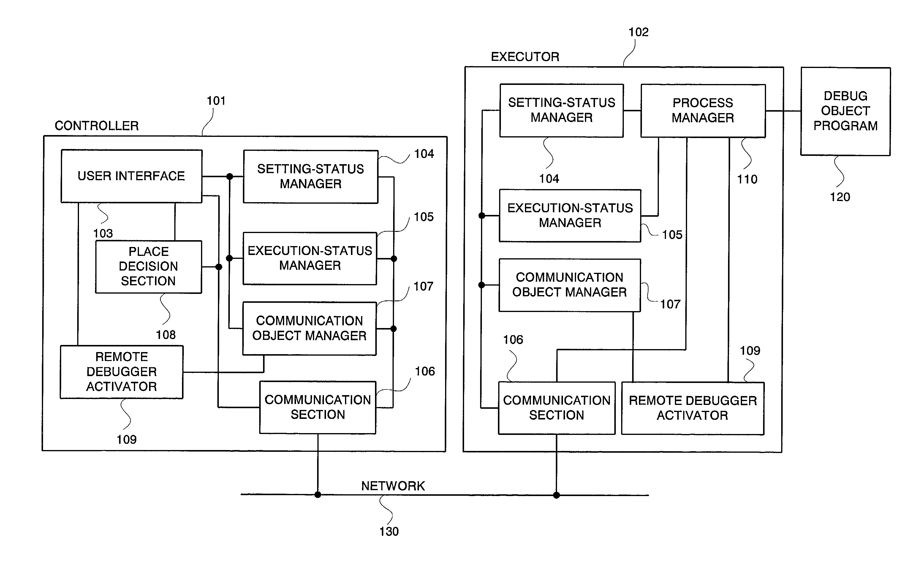
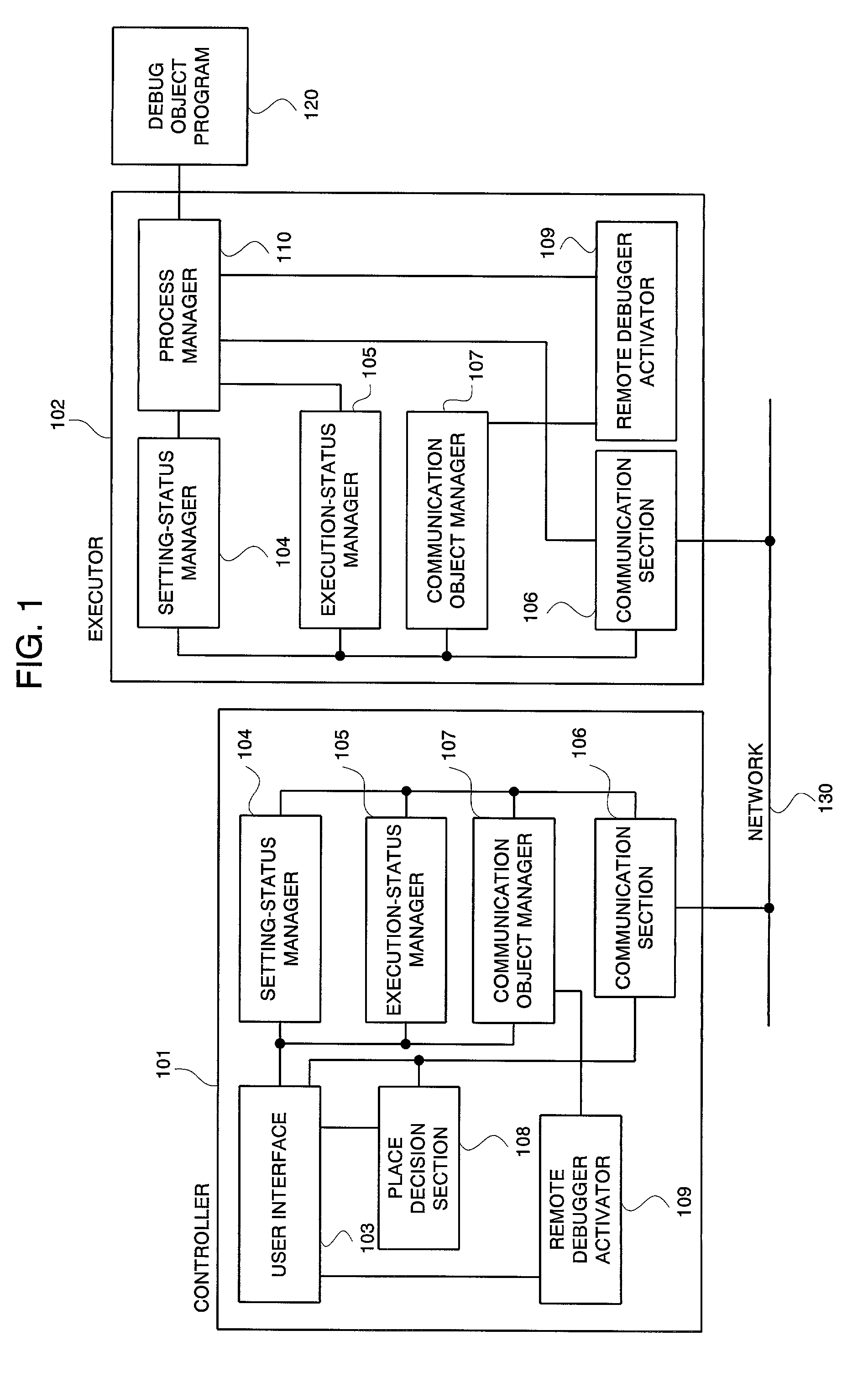
[0042]Embodiments according to the present invention will be described below with reference to the attached drawings. FIG. 1 is a block diagram illustrating a distributed debugger system according to the present invention. Referring to FIG. 1, the debugger system consists of a controller 101 and an executor 102. One or plural controllers 101 and one or plural executors 102 are disposed on a computer and interconnected via a network 130.

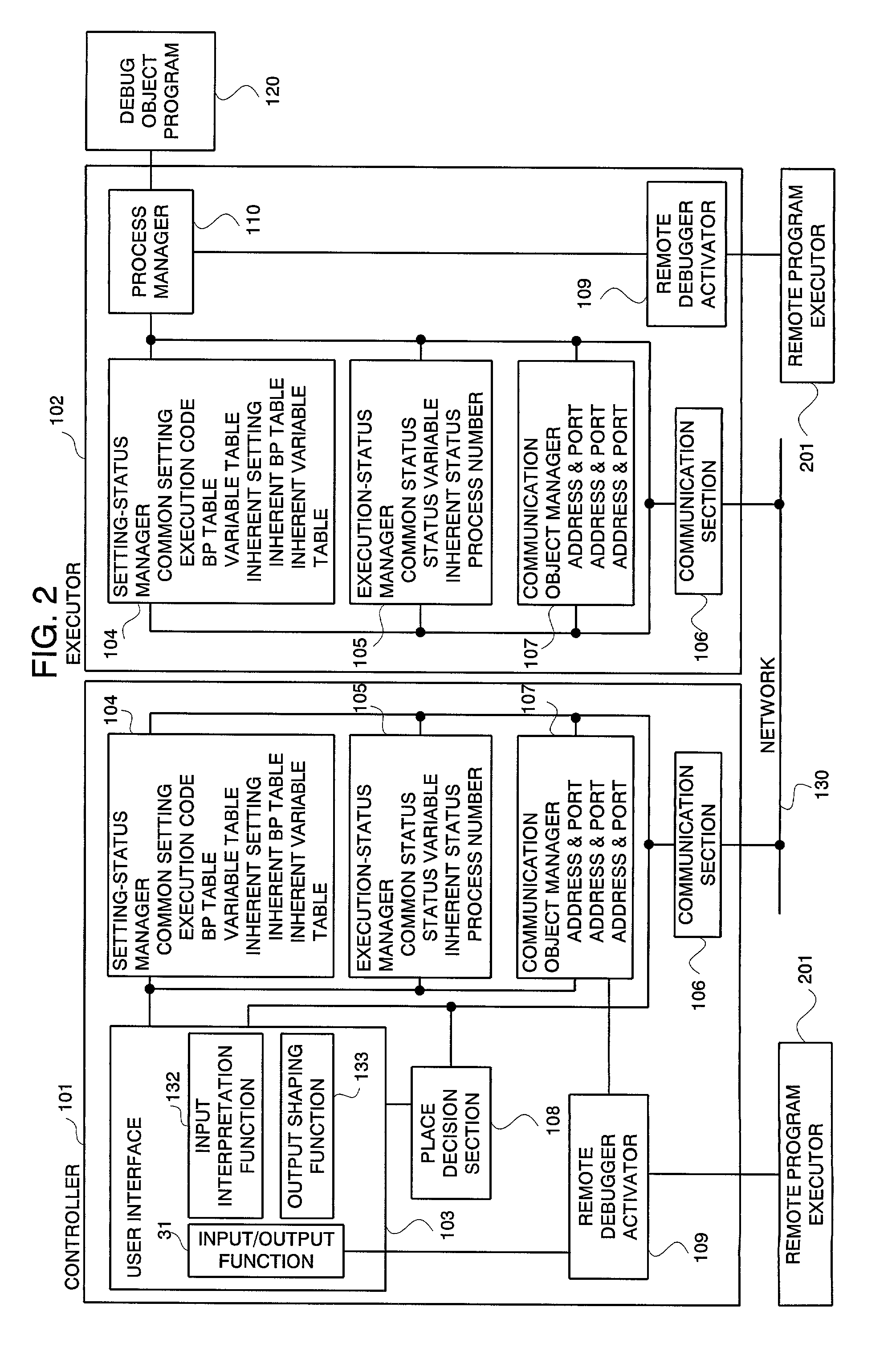
[0043]The controller 101 is part for implementing the input and output process from a user. The controller 101 is receives and processes instructions to a debugger entered by a user. The controller 101 includes a user interface 103 for displaying an output from a debugger to a user, a setting-status manager 104 for managing the setting of a debugger, an execution-status manager 105 for managing the execution status of a debugger, a communication section 106 for notifying the executor and other controllers of the setting status and the executions statu...

second embodiment

[0093]FIG. 12 is a block diagram illustrating the distributed debugger system according to the Referring to FIG. 12, the executor and controller are integrated as a control and execution section 1101. The control and execution section includes a user interface 103, a setting-status manager 104, an execution-status manager 105, a communication section 106, a communication object manager 107, a place decision section 108, a remote debugger activator 109, and a process manager 110. Communications between the input interpretation function and the process manager within the same control and execution section can be accomplished via no communication section.

[0094]Next, the distributed debugger system in the third embodiment will be explained here. In the first embodiment, the debug object program is connected to the distributed debugger system via the process manager and is basically realized as an independent program. The debug object program and the distributed debugger system may be r...

third embodiment

[0095]FIG. 13 is a block diagram illustrating the distributed debugger system according to the Referring to FIG. 13, the distributed debugger system and the debug object program are realized on the same distributed debugger construction foundation. The communication section and the remote debugger activator in the distributed debugger system utilize the communication mechanism provided by the distributed debugger construction foundation. Realizing the distributed debugger system itself on the distributed debugger construction foundation 161 allows the distributed debugger system to be easily assembled.

[0096]In the first and second embodiments, the place where the execution of the debug object program is started is handled as the executor belonging to the computer which includes the controller. However, it is effective that the user can arbitrarily specify the executor when an operation place at the time of debugging is to be separated from an execution place of the object program. ...


PUM


Abstract

For a distributed and transparent debugging environment, a controller and an executor, each which accepts operations from a user, are disposed on each of plural computers. The controller and the executor each has a setting-status manager for managing the setting of a debugger and an execution-status manager for managing the execution status of a debugger. In response to a status change, the controller and the executor each notifies other computers of the content of the change via the network. A process manager manages a debug object program according to the content of setting and sets an operation status change due to detection of a break point to an execution-status manager. Meanwhile, the process manager changes its operation in response to a change in execution status sent from another computer.

Description

BACKGROUND OF THE INVENTION[0001]The present invention relates to a system and method for debugging the software which facilitates the development of software which runs on plural different computers inter-linked via a network. The present invention also relates to a recording medium. Particularly, the present invention relates to a distributed debugger system and debugging method that can easily debug, in execution, programs described for the distributed transparent technique which makes a program recognize as if computers inter-linked via a network are virtually one computer. Moreover, the present invention relates to a recording medium on which control programs are recorded.[0002]Distributed System Configuration Foundation:[0003]Conventionally, in order to construct a distributed system that executes processing between plural computers, a software module is created for each of the computers so that communications are accomplished between the computers. A typical example of the di...

Claims


Application Information

Patent Timeline
Patent Type & Authority Patents(United States)
IPC IPC(8): G06F11/36G06F11/28
CPCG06F11/3664
Inventor KOYAMA, KAZUYA
Owner NEC CORP
Learn More