
Flux converter with power factor correction

a technology of power factor correction and converter, which is applied in the field of flux converter with power factor correction, can solve the problems of affecting the overall size and degree of efficiency, affecting the cost of power supply, and affecting the overall size and efficiency of the power supply,

Inactive Publication Date: 2017-09-05
SIEMENS AG
View PDF19 Cites 0 Cited by
  • Summary
  • Abstract
  • Description
  • Claims
  • Application Information

AI Technical Summary

Benefits of technology

The invention describes a flux converter for efficiently converting network power. One key advantage is that the voltage at the switch is low, even at high input voltages, reducing the strain on components and minimizing the need for protection against power transients. Another advantage is the use of a secondary-side flux choke and rectifier circuit for the output capacitor, which allows for easier dimensioning and compact construction. The invention also includes alternative configurations for the link between the two primary windings and the arrangement of a series circuit consisting of the second primary winding and the second switching element. Overall, the invention provides improved performance and reliability for network power conversion.

Problems solved by technology

These design measures can comprise a considerable proportion of the cost of a power supply.
In addition, the overall size and the degree of efficiency are negatively influenced as a consequence of additional power losses.
This only makes sense in the case of low power outputs because otherwise the corresponding chokes are too large and heavy.
In addition to the costs of the chokes, their power loss must be taken into consideration.
This conventional method is not well suited for wide input voltage ranges on account of the variance in the maximum input current associated therewith.
In addition to the complexity, a disadvantage is the output voltage of such a PFC circuit, which in principle exceeds the maximum network voltage, as a result whereof problems can occur primarily with regard to high network input voltages in respect of component loadings and insulation voltages.
Active PFC circuits have the disadvantage that they must be provided in addition to the actual converter.
Compared with converters not having PFC functionality, this means significant additional expenditure and additional losses.

Method used


Image

  • Flux converter with power factor correction
  • Flux converter with power factor correction
  • Flux converter with power factor correction

Examples


Embodiment Construction

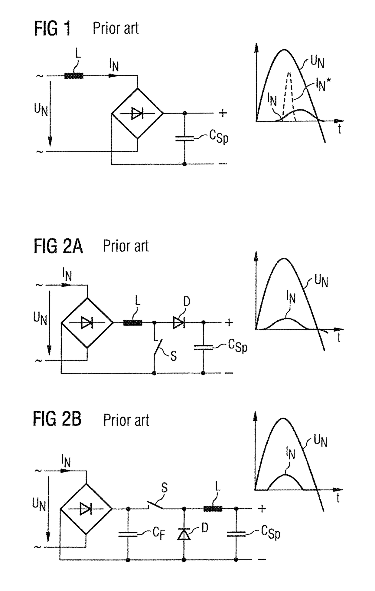
[0041]FIGS. 1-3 show conventional PFC circuits which convert an AC input voltage into a DC voltage of an intermediate circuit. With regard to a passive circuit (FIG. 1), a sufficiently large inductance L is arranged upstream of a rectifier unit. The conduction angle is increased in this manner compared with the original current profile IN*, whereby a phase displacement however occurs which is to be taken into consideration.

[0042]The conventional active circuits (FIGS. 2a and 2b) comprise a clocked switch S by which it is possible to also influence the phasing of the current IN in addition to the conduction angle.

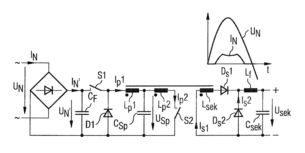
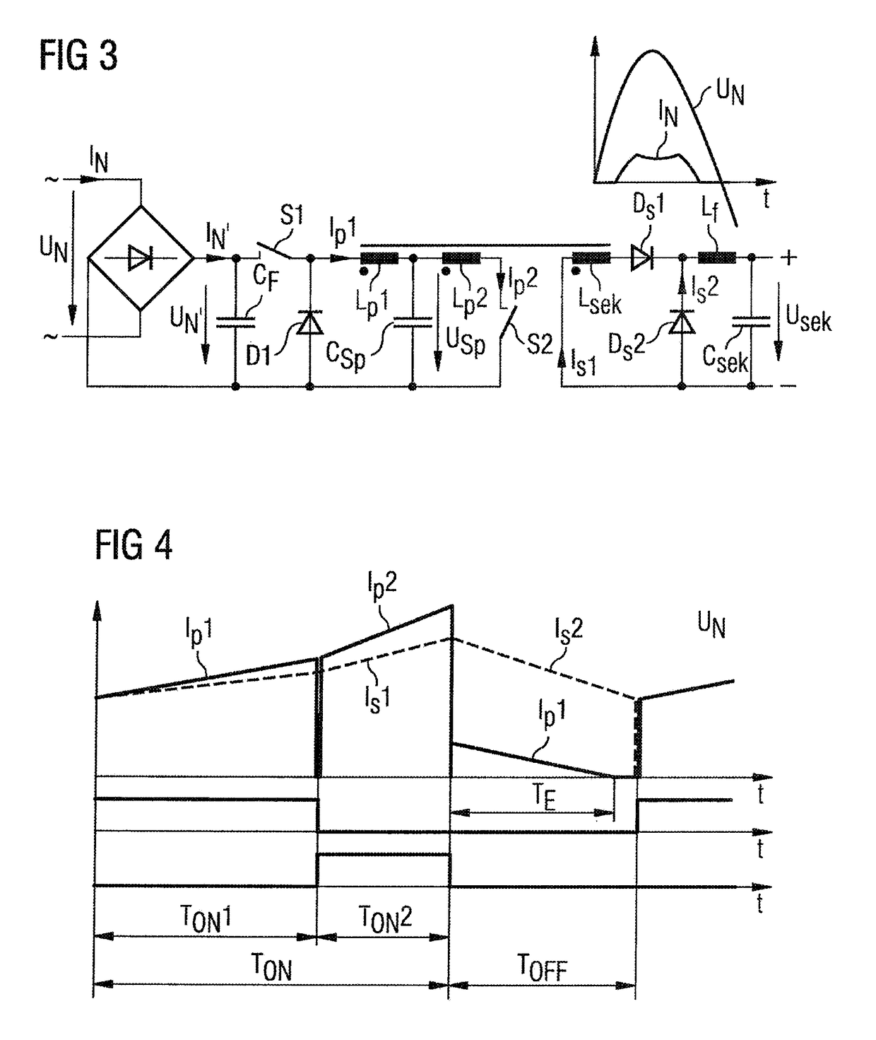
[0043]The flux converter illustrated in FIG. 3 comprises an input-side rectifier bridge which is connected to an AC voltage UN and converts an AC current IN into a rectified current IN′. Connected downstream of the rectifier bridge is a filter capacitor CF which is small in dimension in respect of the frequency of the AC voltage UN. This filter capacitor CF can advantageousl...


PUM


Abstract

A flux converter for converting an input-side alternating current into an output-side DC current, wherein a power factor correction is provided and the flux converter comprises a transformer having at least two serially arranged primary windings and a secondary winding wound in same direction. In addition, a first switch is used to switch a storage capacitor in series with a first primary winding to the alternating current in a clocked manner via rectification elements and a second primary winding can be switched to the storage capacitor in a clocked manner by a second switch.

Description

CROSS-REFERENCE TO RELATED APPLICATIONS[0001]This is a U.S. national stage of application No. PCT / EP2010 / 067878 filed 22 Nov. 2010. Priority is claimed on Austrian Application No. A1907 / 2009 filed 2 Dec. 2009, the content of which is incorporated herein by reference in its entirety.BACKGROUND OF THE INVENTION[0002]1. Field of the Invention[0003]The invention relates to flux converters and, more particularly, to a flux converter for converting an input-side AC voltage into an output-side DC voltage to provide a power factor correction. The invention furthermore relates to a method for operating such a flux converter.[0004]2. Description of the Related Art[0005]Generally, converters used in normal network power supplies exhibit input currents having significant harmonics or a power factor well below one. The reason for this lies in the requirement to recharge a storage capacitor on the DC side by a two-way rectifier. Short, needle-shaped current peaks are the result. Without additiona...

Claims


Application Information

Patent Timeline
Patent Type & Authority Patents(United States)
IPC IPC(8): H02M1/42
CPCH02M1/4258Y02B70/126Y02P80/112Y02B70/10Y02P80/10
Inventor AUGESKY, CHRISTIAN
Owner SIEMENS AG
Learn More