
Detection of faults in an injector arrangement

a fuel injector and fault technology, applied in hydrodynamic testing, electric control, instruments, etc., can solve problems such as short circuit faults, failures of drive circuits, and catastrophic failures of engines, and achieve no net

Inactive Publication Date: 2008-12-25
DELPHI INT OPERATIONS LUXEMBOURG S A R L
View PDF5 Cites 33 Cited by
  • Summary
  • Abstract
  • Description
  • Claims
  • Application Information

AI Technical Summary

Benefits of technology

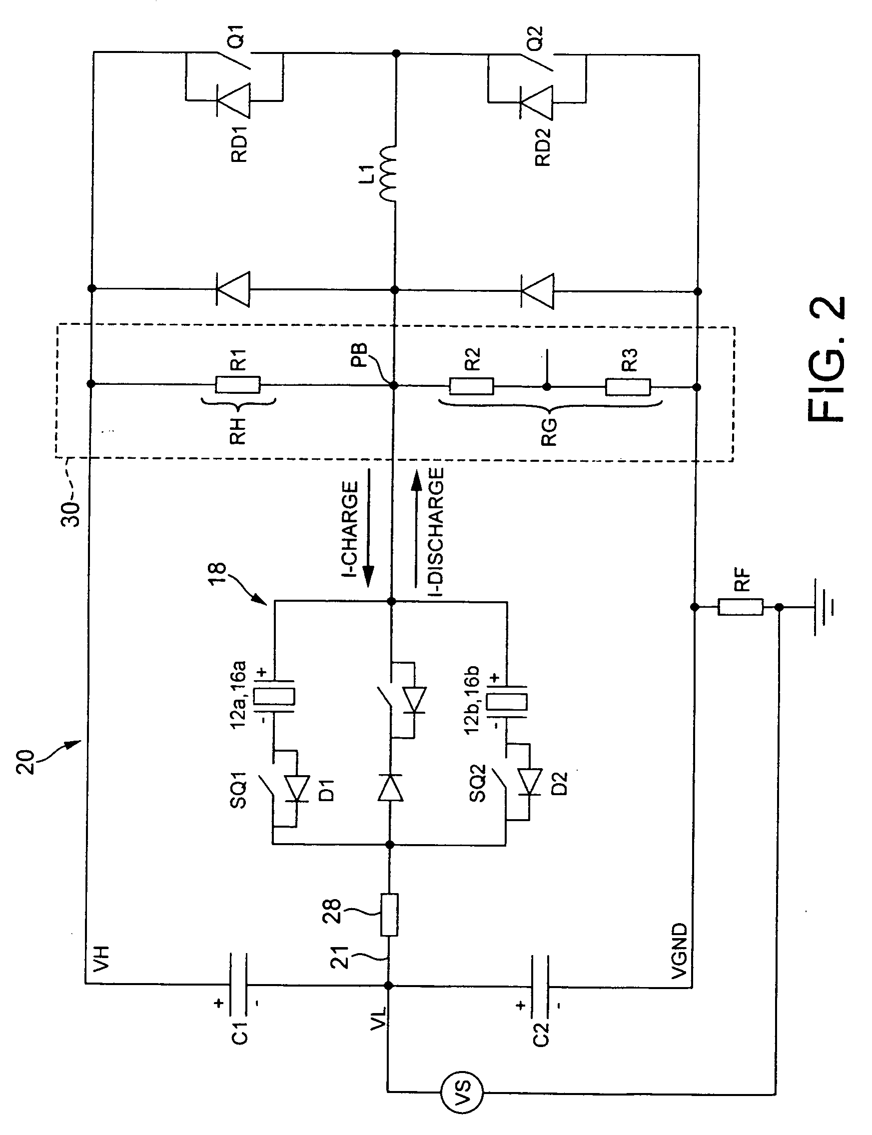
The invention provides a method for detecting faults in an injector arrangement at engine start-up using a piezoelectric fuel injector. The method involves measuring the bias voltage at the injector arrangement and comparing it to a predicted voltage. If the bias voltage is within a predetermined tolerance of the predicted voltage, the injector is considered to be in good condition. The method can detect high side to ground short circuits with a wide range of resistances. The method can be used in drive circuits for discharge-to-inject or charge-to-inject type injectors. The method can also be used in a drive circuit for a single injector or multiple injectors. The resistive bias network used in the method can be a resistive bias network or a combination of resistors. The method can be used in any circuit that uses a charge circuit or a discharge circuit for the injectors. The method can also be used in a drive circuit for a battery that is used to start the engine. The method can be used to detect minor or major faults and can alert the user with a warning light or other alert mechanism.

Problems solved by technology

Like any circuit, faults may occur in a drive circuit.
In safety critical systems, such as diesel engine fuel injection systems, a fault in the drive circuit may lead to a failure of the injection system, which could consequentially result in a catastrophic failure of the engine.
Such faults include short circuit faults and open circuit faults in the piezoelectric actuators of the fuel injectors.

Method used


Image

  • Detection of faults in an injector arrangement
  • Detection of faults in an injector arrangement
  • Detection of faults in an injector arrangement

Examples


Embodiment Construction

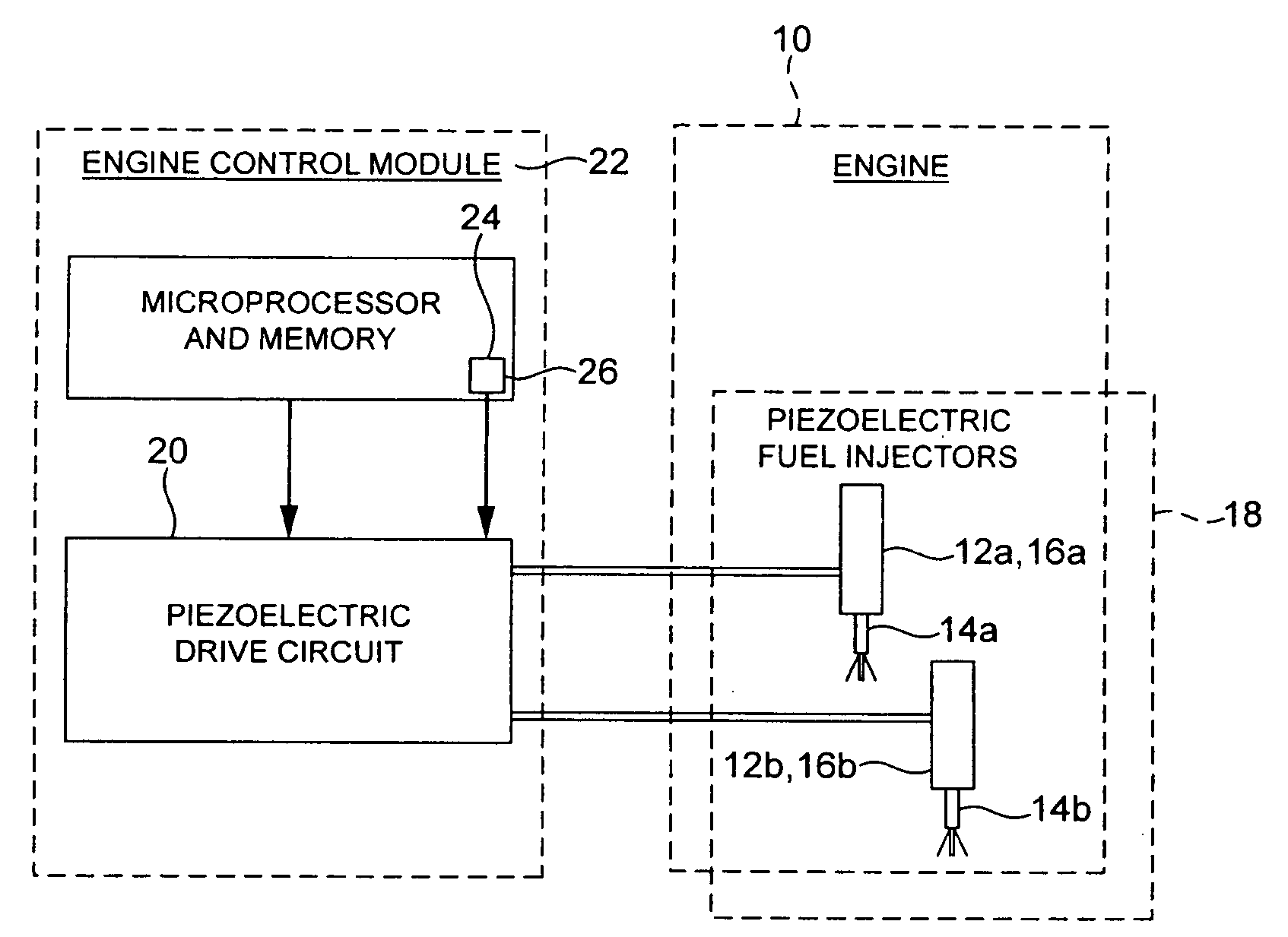
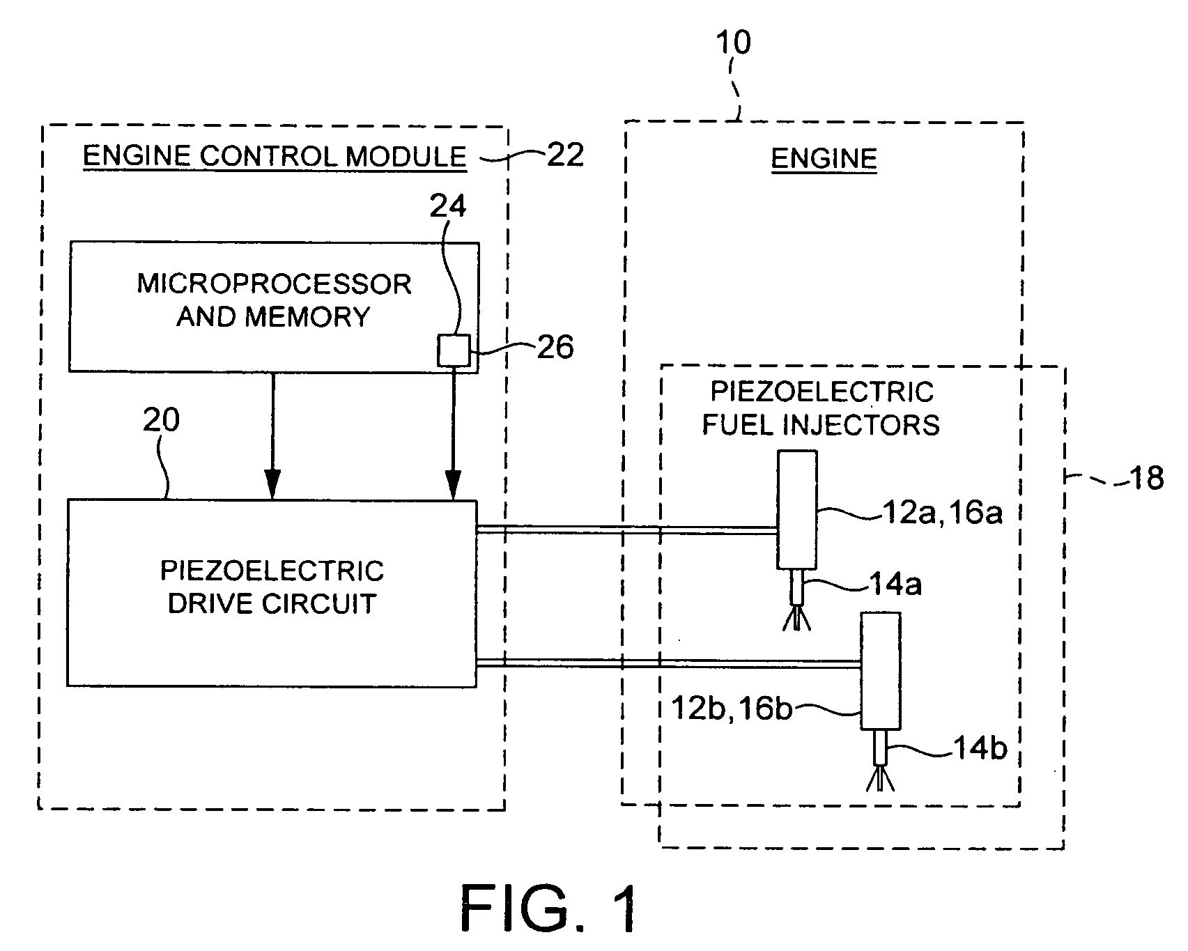
[0071]Referring to FIG. 1, an engine 10, such as an automotive vehicle engine, is shown having a fuel injector arrangement comprising a first fuel injector 12a and a second fuel injector 12b. The fuel injectors 12a, 12b each have an injector valve needle 14a, 14b respectively, and a piezoelectric actuator 16a, 16b respectively. The piezoelectric actuators 16a, 16b are operable to cause the injector valve needle 14a, 14b of the associated injector 12a, 12b to open and close to control the injection of fuel into an associated cylinder of the engine 10. The fuel injectors 12a, 12b may be employed in a diesel internal combustion engine to inject diesel fuel into the engine 10, or they may be employed in a spark ignited internal combustion engine to inject combustible gasoline into the engine 10.

[0072]The fuel injectors 12a, 12b form an injector bank 18 and are controlled by a drive circuit 20. In practice, the engine 10 may be provided with more than one injector bank 18, and each injec...


PUM


Abstract

A fault detection method for detecting short circuit faults in an injector arrangement at engine start-up. The injector arrangement comprises one or more piezoelectric fuel injectors, which are connected in a drive circuit. In one aspect of the invention, the potential at a bias point in the drive circuit is determined and compared with a predicted voltage. A short circuit fault signal is generated if the potential at the bias point is not within a predetermined tolerance voltage of the predicted voltage. In another aspect of the invention, a first charge pulse is applied to the injectors to charge the injectors. A discharge current path is provided during a delay period following the first charge pulse by closing a discharge switch. A faulty injector will discharge through the discharge current path during the delay period. A second charge pulse is applied to the injectors following the delay period. Current flow is sensed during the second charge pulse, and a short circuit warning signal is generated if the current flow during the second charge pulse exceeds a predetermined threshold current.

Description

TECHNICAL FIELD[0001]The present invention relates to a method for detecting faults in a fuel injector arrangement, and particularly to a method for detecting short circuits in a fuel injector arrangement at engine start-up.BACKGROUND TO THE INVENTION[0002]Automotive vehicle engines are generally equipped with fuel injectors for injecting fuel (e.g. gasoline or diesel fuel) into the individual cylinders or intake manifold of the engine. The engine fuel injectors are coupled to a fuel rail which contains high pressure fuel that is delivered by way of a fuel delivery system. In diesel engines, conventional fuel injectors typically employ a valve needle that is actuated to open and to close in order to control the amount of fluid fuel metered from the fuel rail and injected into the corresponding engine cylinder or intake manifold.[0003]One type of fuel injector that offers precise metering of fuel is the piezoelectric fuel injector. Piezoelectric fuel injectors employ piezoelectric ac...

Claims


Application Information

Patent Timeline
Patent Type & Authority Applications(United States)
IPC IPC(8): G01R31/308
CPCF02D41/062F02D41/2096F02D41/221F02D2041/2006F02D2041/2051F02D2041/2058F02D2041/2072F02D2041/2093F02M51/0603
Inventor PERRYMAN, LOUISA J.
Owner DELPHI INT OPERATIONS LUXEMBOURG S A R L
Learn More