
Connecting structure of crimp terminal and electric wire

a technology of connecting structure and crimp terminal, which is applied in the direction of coupling contact member, connection contact member material, coupling device connection, etc., can solve problems such as galvanic corrosion, and achieve the effect of preventing the reduction of sealing property and reducing the extrusion of electric wir

Active Publication Date: 2017-09-05
YAZAKI CORP
View PDF5 Cites 11 Cited by
  • Summary
  • Abstract
  • Description
  • Claims
  • Application Information

AI Technical Summary

Benefits of technology

The present invention aims to solve the issue of electric wire extrusion and sealing property reduction during the connection between a crimp terminal and an electric wire. The technical effect is to provide a connection structure that reduces the risk of these issues.

Problems solved by technology

In other words, galvanic corrosion occurs.

Method used


Image

  • Connecting structure of crimp terminal and electric wire
  • Connecting structure of crimp terminal and electric wire
  • Connecting structure of crimp terminal and electric wire

Examples


embodiment

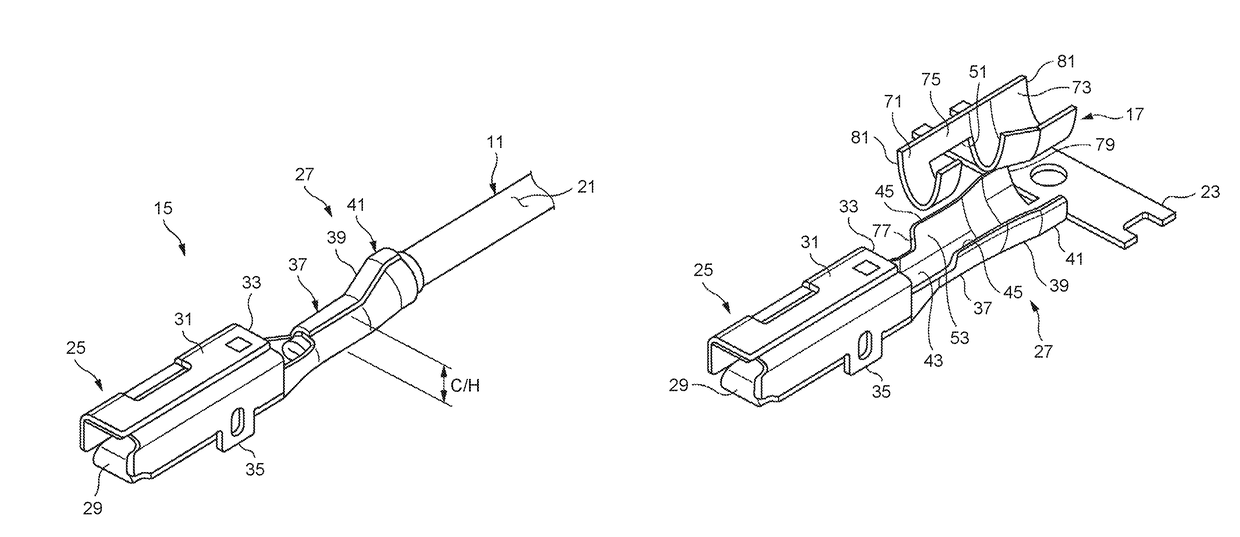
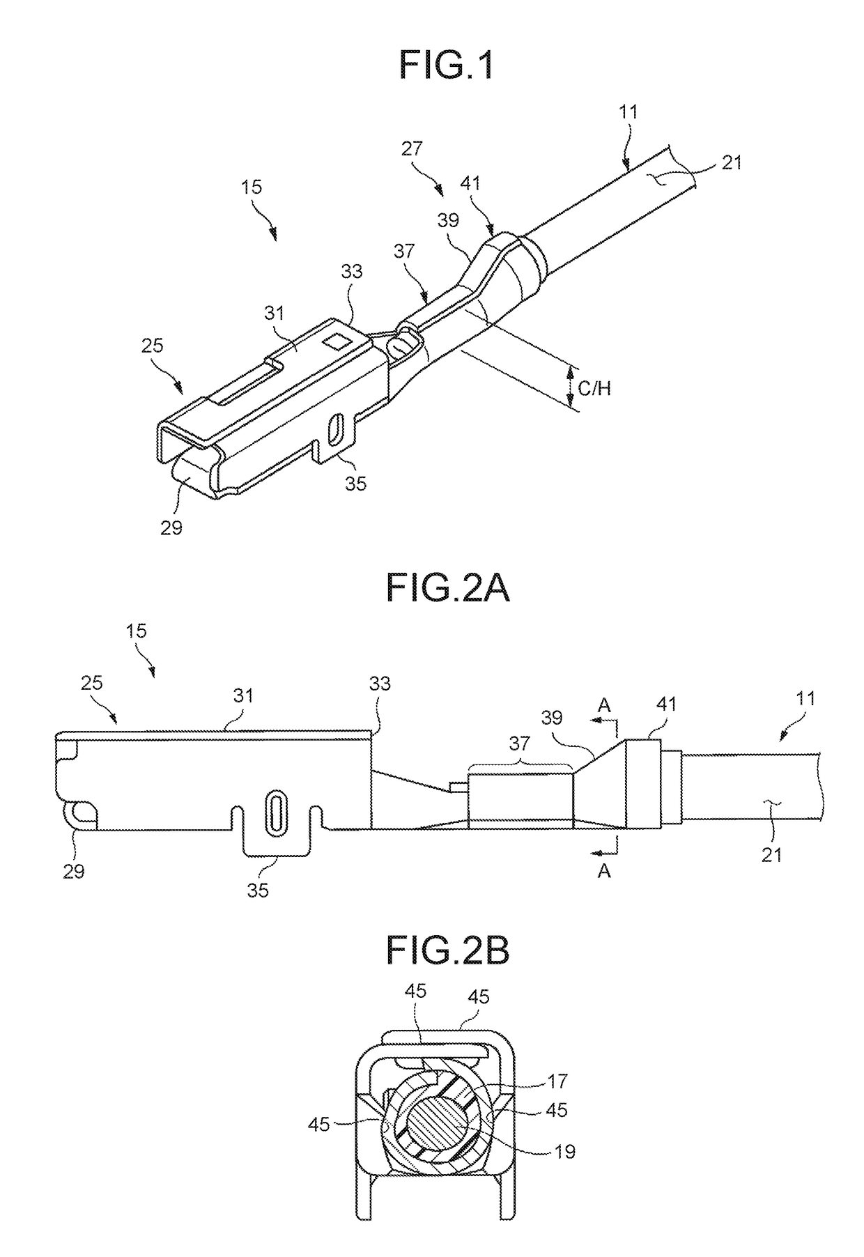
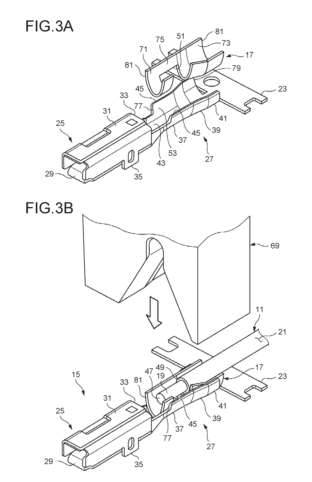
[0022]One embodiment of the present invention will be explained with reference to the accompanying drawings. As illustrated in FIGS. 1, 2A, and FIG. 2B, a connecting structure of a crimp terminal and an electric wire according to the embodiment includes an electric wire 11, a crimp terminal 15, and a water stop sheet 17 that is a water-proofing material.

[0023]The electric wire 11 includes a conductor 19 covered with an insulating coating 21. The conductor 19 is formed by twisting together a plurality of element wires. The conductor 19 may be a single wire. For example, aluminum and an aluminum alloy are used for the conductor 19. A synthetic resin is used for the coating 21. Examples of the synthetic resin include a resin formed by adding a flame retardant to a base such as polyvinyl chloride (PVC), polyolefin, and polyamide.

[0024]The crimp terminal 15 is formed by applying press working (punch working and folding working) to a sheet of metal plate made of a conductive metal (copper...


PUM


Abstract

A structure for connecting a crimp terminal and an electric wire includes: a crimp terminal that includes a conductor crimping portion and a coating crimping portion serially and includes an electric wire connector that is to be crimped to the electric wire; and a water stop sheet having an opening for bringing a conductor into contact with the conductor crimping portion, and laid between the electric wire connector and the electric wire. When a joint is swaged and crimped, the swaged and crimped joint has a second included angle θ2 between the bottom plate and a second line that is larger than a first included angle θ1 between the bottom plate and a first line in a cross section that is perpendicular to a bottom plate of the electric wire connector and that includes an electric wire axial line.

Description

CROSS-REFERENCE TO RELATED APPLICATION[0001]This application is a continuation application of International Application PCT / JP2015 / 057636, filed on Mar. 16, 2015, and designating the U.S., the entire contents of which are incorporated herein by reference.BACKGROUND OF THE INVENTION[0002]1. Field of the Invention[0003]The present invention relates to a connecting structure of a crimp terminal and an electric wire.[0004]2. Description of the Related Art[0005]Reduction in the weight of a vehicle has a great influence on improvement of fuel consumption. Currently, reduction in carbon dioxide emission is required, and especially in an electric vehicle and a hybrid vehicle where the amount of wire harnesses used therein is larger than that in a gasoline-powered vehicle, it is preferable that an electric wire made of aluminum and an aluminum alloy of lightweight materials be used for a wire harness. However, in an aluminum-made electric wire made of aluminum or an aluminum alloy being crim...

Claims


Application Information

Patent Timeline
Patent Type & Authority Patents(United States)
IPC IPC(8): H01R4/10H01R4/62H01R13/52H01R4/18H01R13/11
CPCH01R4/62H01R4/185H01R13/5216H01R13/113
Inventor AOKI, HIROSHIOHTAKA, KAZUTO
Owner YAZAKI CORP
Learn More