Method and device for observing and analysing optical singularities in glass containers

a glass container and optical singularity technology, applied in the direction of measurement devices, material analysis through optical means, instruments, etc., can solve the problems of not being able to observe the white area corresponding to the beads in the image, not being able to observe the container in reflection, and presenting abnormal refraction and/or reflection effects

Active Publication Date: 2017-08-29
MSC & SGCC
View PDF15 Cites 1 Cited by
  • Summary
  • Abstract
  • Description
  • Claims
  • Application Information

AI Technical Summary

Benefits of technology

[0016]The invention seeks to provide a novel technique enabling optical singularities carried at the surface or in the wall of a container to be observed and analyzed, and making this possible regardless of the transmittance of the material constituting the container.

Problems solved by technology

Specifically, these optical singularities mainly present a refraction and / or reflection effect that is abnormal compared with their neighborhood.
Although such apparatus is suitable for detecting light-refracting defects in transmission, it is not suitable for acquiring images of the container in reflection, in particular for the purpose of analyzing marks or codes made on the surfaces of containers that present low or high transmittance.
Such systems operate only on portions in relief that are of relatively large size and by putting the containers into rotation, which is expensive and disturbs manufacturing lines, which generally involve travel that is linear.
When portions in relief are small, e.g. because the molds are worn, the white areas corresponding to the beads in the image becomes small or even not observable.
That system thus requires the container to be rotated, giving rise to the numerous drawbacks described above.
It is not suitable for reading codes on traveling containers.
Nevertheless, that system requires the container to be rotated and it is not suitable for reading codes on traveling containers.

Method used


Image

  • Method and device for observing and analysing optical singularities in glass containers
  • Method and device for observing and analysing optical singularities in glass containers
  • Method and device for observing and analysing optical singularities in glass containers

Examples


Embodiment Construction

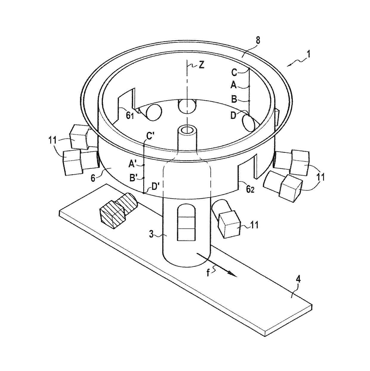
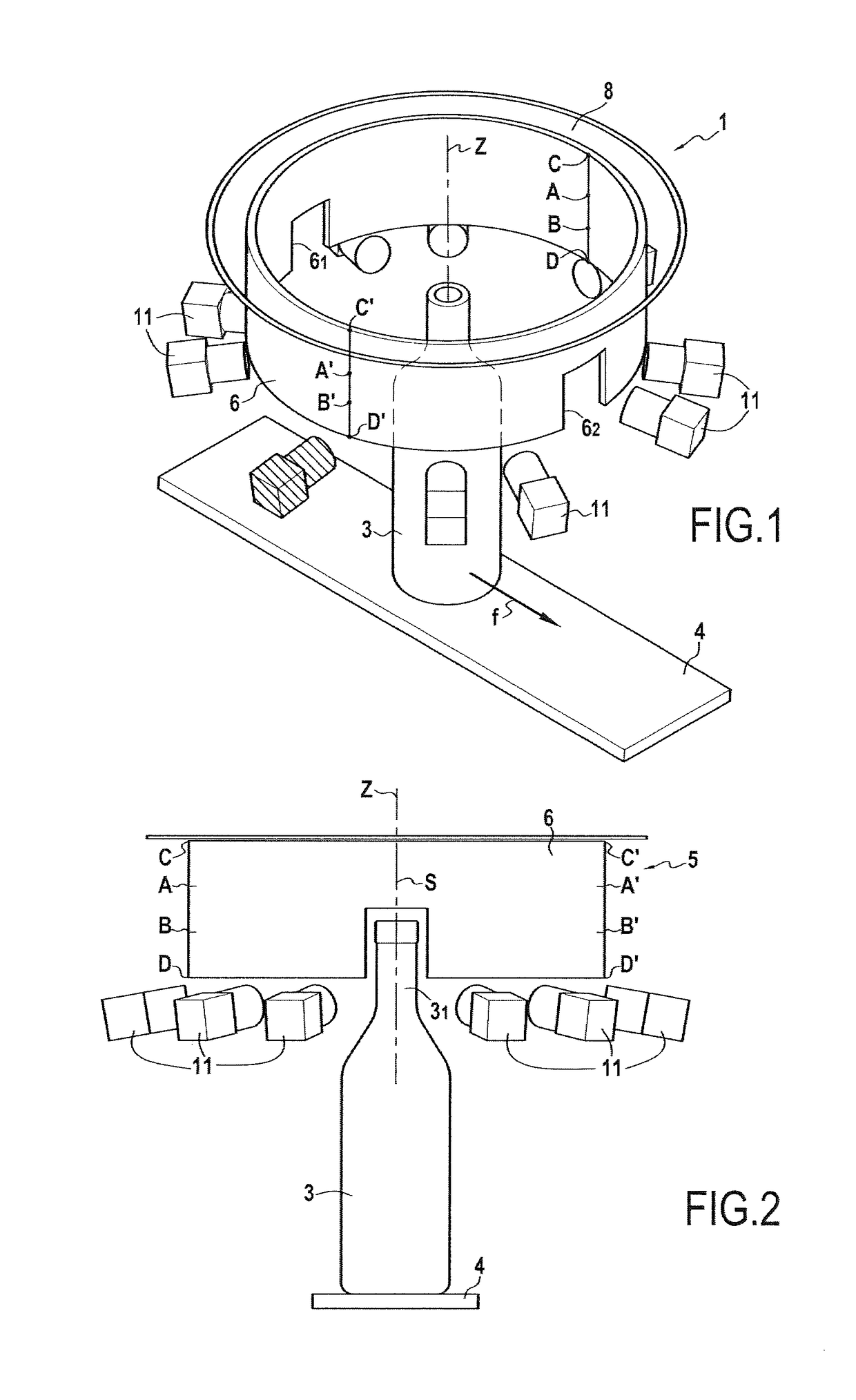
[0071]As can be seen more clearly in FIGS. 1 to 3, the invention relates to a device 1 for observing and analyzing optical singularities 2 that deflect light, which singularities are located at the surface of or within the wall of a glass container 3 that presents an axis of symmetry S. In a preferred embodiment, the container 3 is caused to travel along a curvilinear path, or still more simply in translation along a travel direction represented by arrow f so as to enable it to be observed by the device 1. The containers 3 are thus moved for example by means of a conveyor 4 so as to travel in succession past the device 1.

[0072]In the embodiment shown in the drawings, the device 1 is particularly suitable for observing optical singularities in the necks 31 of containers. Concerning optical singularities, provision may be made to observe and analyze a code, e.g. etched by means of a laser on the neck, or an identifying mark, or a pattern made by molding. Naturally, the device may be a...


PUM

PropertyMeasurementUnit
angleaaaaaaaaaa
thicknessesaaaaaaaaaa
diameteraaaaaaaaaa

Abstract

A method of observing and analyzing optical singularities includes illuminating an outside of a container by using a light-emitting surface of axial symmetry around a vertical axis (Z) parallel to the axes of symmetry of the containers, with a property of the emission that is detectable by the acquisition system(s) varying along a generator line of the light-emitting surface. For containers of low transmittance, taking the view image of the container portion by the image acquisition device receiving light beams comes from a portion of the light-emitting surface situated on the same side of the container. For containers of high transmittance, taking the view of the container portion by the image acquisition device receiving light beams comes from a portion of the light-emitting surface that is diametrically opposite relative to the container.

Description

FIELD OF THE INVENTION[0001]The invention relates to the technical field of observing and analyzing optical singularities carried by glass containers, such as bottles, pots, and flasks.BACKGROUND ART[0002]A few concepts of optical physics or mathematics are summarized below. In optics, the luminous exitance of a point of a light-emitting surface is the flux emitted into a half-space by unit area of the emissive surface centered at the point. This concept is sometimes also referred to as emittance or as radiance. A gradient is the derivative along one or more directions of a magnitude, in other words a gradient means that the magnitude varies. A luminous exitance gradient means that luminous exitance varies along the emitting surface. Likewise, a color gradient means that the color of the light emitted varies along the emitting surface. A diffuser is an element made of transparent or translucent material that diffuses light within its bulk and / or at its surface.[0003]The term “singul...

Claims


Application Information

Patent Timeline
Patent Type & Authority Patents(United States)
IPC IPC(8): G01N21/90B07C5/34G01N21/84
CPCG01N21/9036B07C5/3408G01N21/909G01N2021/845
Inventor LECONTE, MARCFAYOLLE, LUBINPIROT, ERIC
Owner MSC & SGCC
Why Eureka
Try Eureka