
Thermally shielding body with temperature-resistant fastening points, and method for producing it

a technology of thermal shielding body and fastening point, which is applied in the direction of exhaust treatment, vehicle components, mechanical equipment, etc., can solve the problems that conventional shielding elements made from aluminium such as acoustically or thermally shielding plates cannot be fastened directly to particularly hot conditions, and achieve good thermal shielding of fastening elements, greater heat resistance, and greater heat resistance

Inactive Publication Date: 2017-07-04
FEDERAL MOGUL SEALING SYST
View PDF16 Cites 2 Cited by
  • Summary
  • Abstract
  • Description
  • Claims
  • Application Information

AI Technical Summary

Benefits of technology

The patent describes a way to reinforce a thermally shielding plate made from aluminum by adding a metal-plate element with higher heat resistance. This can be done by extending the metal-plate element along the edge of the thermally shielding plate or connecting them in a point-wise, material-to-material manner. This helps increase the vibration resistance of the thermally shielding body and also allows for better cooling of the connection. The metal-plate element can also be connected to the thermally shielding plate by ultrasonic welding or overlap, and in both cases the connection can be thermally offloaded. The metal-plate element can also have a structure to minimize heat transfer from the hot component by providing a point-wise or line-wise contact surface.

Problems solved by technology

Conventional shielding elements made from aluminium such as acoustically or thermally shielding plates often cannot be fastened directly to particularly hot components such as an exhaust manifold, a turbocharger, etc, since under operating conditions these components reach temperatures that are higher than the melting point of aluminium.

Method used


Image

  • Thermally shielding body with temperature-resistant fastening points, and method for producing it
  • Thermally shielding body with temperature-resistant fastening points, and method for producing it
  • Thermally shielding body with temperature-resistant fastening points, and method for producing it

Examples


Embodiment Construction

[0030]In both the figures and their description the same or similar reference symbols are used to designate the same or similar elements.

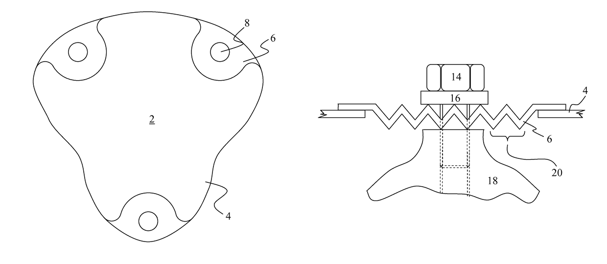
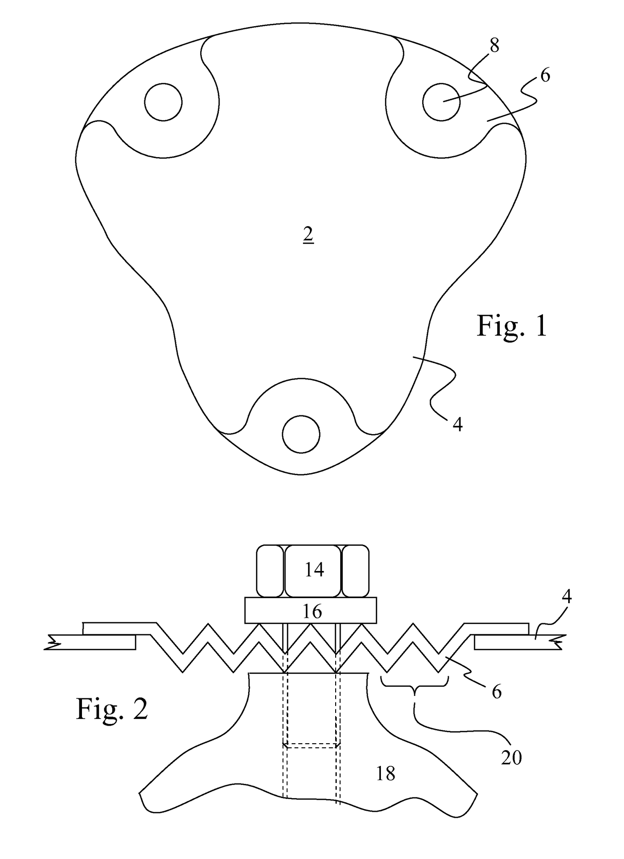
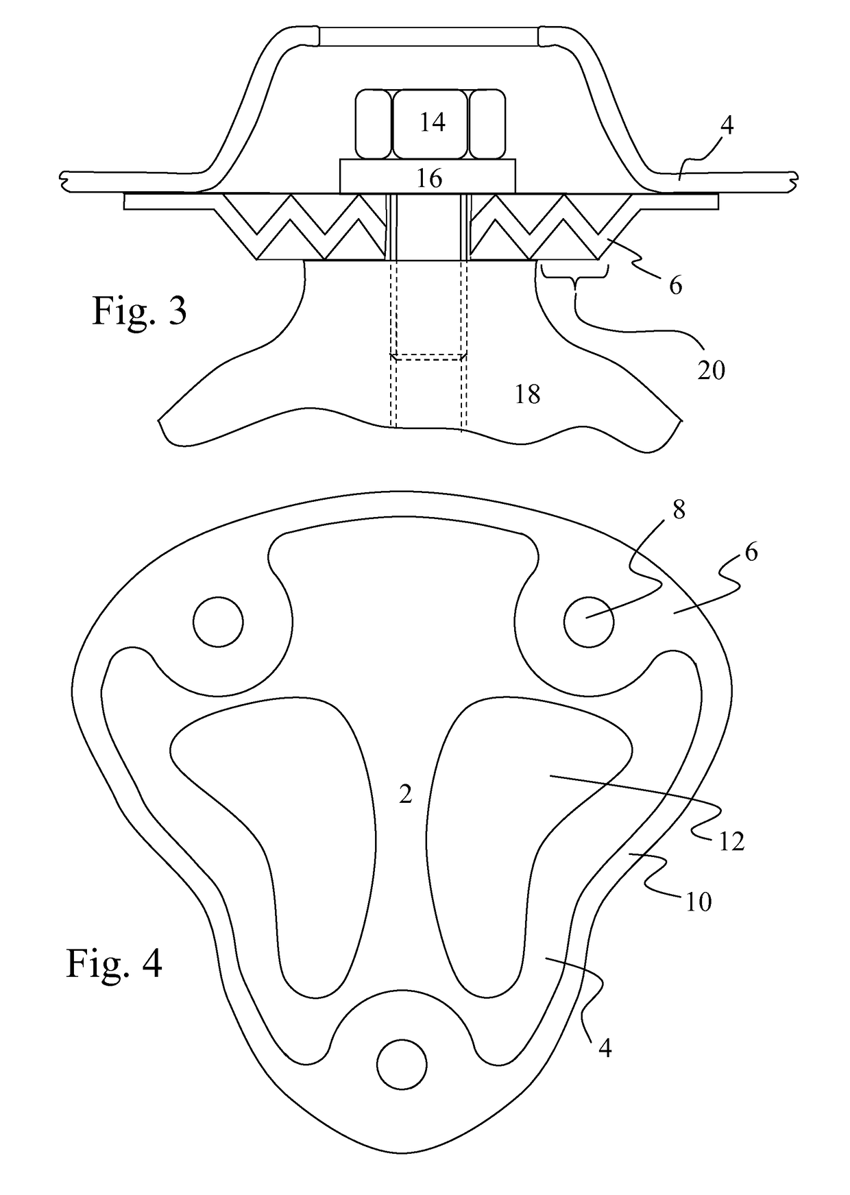
[0031]FIG. 1 shows a view of an inventive thermally shielding body 2 that is provided with three temperature-resistant fastening points 8. The thermally shielding body 2 comprises a single- or multi-layer thermally shielding plate 4 made from aluminium. The thermally shielding plate 4 made from aluminium is provided with a cut-out in the region of at least one fastening point 8. A metal-plate element 6 with greater heat resistance is arranged in the cut-out, which metal-plate element is connected in a material-to-material manner with the thermally shielding plate 4 at an edge of the cut-out or the metal-plate element 6. The at least one temperature-resistant fastening point 8 is thereby arranged on the metal-plate element 6 with greater heat resistance. As can be discerned from the drawing, the edge of the cut-out of the thermally shielding plate 4...


PUM

PropertyMeasurementUnit
total thicknessaaaaaaaaaa
thicknessaaaaaaaaaa

Abstract

Thermally shielding body having at least one temperature-resistant fastening point, comprising a thermally shielding plate made from aluminum, wherein the thermally shielding plate made from aluminum has a cut-out in the region of at least one fastening point, wherein a metal-plate element with greater heat resistance is arranged in the cut-out, which metal-plate element is connected in a material-to-material manner to the thermally shielding plate at the edge of the cut-out or of the metal-plate element, wherein the at least one heat-resistant fastening point in arrange on the metal-plate element with greater heat resistance, and at method for producing the thermally shielding body.

Description

BACKGROUND OF THE INVENTION[0001]1. Technical Field[0002]The present invention concerns a thermally shielding body with temperature-resistant fastening points.[0003]2. Related Art[0004]Conventional shielding elements such as acoustically or thermally shielding plates are, for example, of known art from the documents EP 1 609 681 A1, DE 10 2005 015 246 A1, DE 10 2005 015 244 A1, DE 10 2005 006 577 A1 and DE 102 47 641 B3.[0005]Conventional shielding elements made from aluminium such as acoustically or thermally shielding plates often cannot be fastened directly to particularly hot components such as an exhaust manifold, a turbocharger, etc, since under operating conditions these components reach temperatures that are higher than the melting point of aluminium.[0006]In the prior art there exists therefore a requirement to be able to mount shielding bodies made from aluminium also directly onto components whose operating temperature lies above the melting point of aluminium of approx. ...

Claims


Application Information

Patent Timeline
Patent Type & Authority Patents(United States)
IPC IPC(8): B60R13/08F01N13/14F01N13/18
CPCB60R13/0876F01N13/148F01N13/1855F01N2260/20Y10T29/4935
Inventor KRUS, RALF
Owner FEDERAL MOGUL SEALING SYST
Learn More