
Electric power steering controller

a technology of electric power steering and controller, which is applied in the direction of electric steering, power driven steering, vehicle components, etc., can solve the problems of increasing the estimated load, increasing the steering torque, and increasing the steering angle under the influence of friction, so as to reduce the friction influence

Inactive Publication Date: 2017-06-27
DENSO CORP
View PDF6 Cites 3 Cited by
  • Summary
  • Abstract
  • Description
  • Claims
  • Application Information

AI Technical Summary

Benefits of technology

The present invention provides an electric power steering controller that reduces the impact of friction in the stealing system on the driver's feel. This is achieved by correcting the target steer torque based on the steer angle to establish a stable steering feel in various environments. The technical effect is a more robust and stable steering control for drivers.

Problems solved by technology

Further, an increase of the assist torque instruction value that is used for the estimation of the load of the steering mechanism leads to an increase of the estimated load.
In other words, a returnability of the steering wheel (i.e., steering angle returning to 0 degree) becomes poor under the influence of the friction.
In other words, when steering the steering wheel on a low μ road (e.g., in a turning state or a returning state), the increase of the steer torque is devastatingly large in comparison to a low friction time / case.
This also means that the returnability of the steering wheel back to neutral position becomes poor (i.e., is worsened) during a high friction time in comparison to the low friction time.
Further, in a low-speed travel time of the vehicle, a self-aligning torque is small as compared with a high-speed travel time, which also leads to an increase of the friction influence in the steering system components in the low-speed travel time as compared with the high-speed travel time.
Therefore, as compared with the high-speed travel time, the steer torque for steering the steering wheel increases in the low-speed travel time, and the returnability of the steering angle worsens.

Method used


Image

  • Electric power steering controller
  • Electric power steering controller
  • Electric power steering controller

Examples


first embodiment

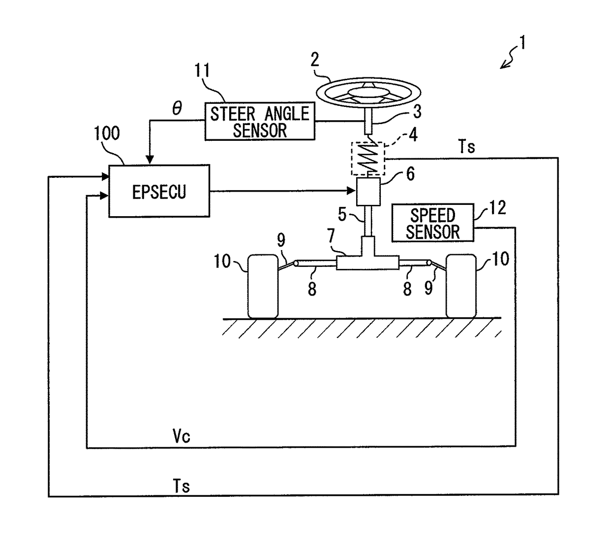
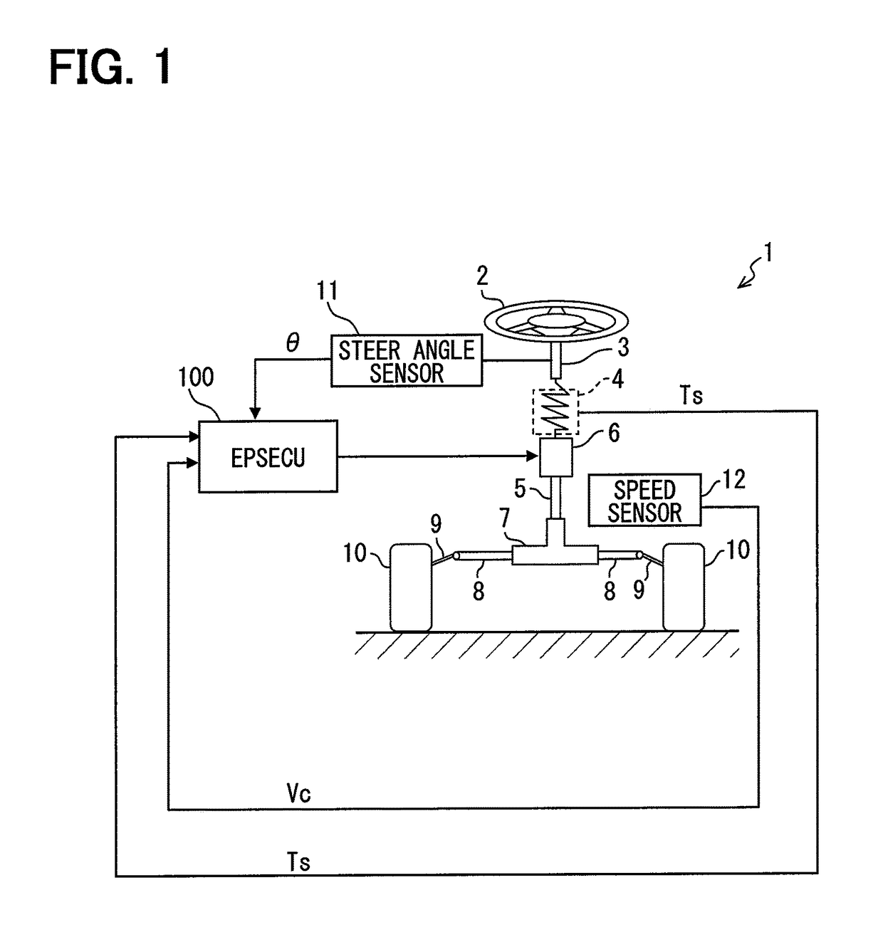
[0032]The first embodiment of the present disclosure is described in the following with reference to the drawings. An electric power steering system 1 shown in FIG. 1 assists a driver's operation of a steering wheel 2 by using a motor 6.

[0033]The steering wheel 2 is attached to one end of a steering shaft 3 which is an input shaft. A torque sensor 4 is connected to the other end of the steering shaft 3, and an intermediate shaft 5 is connected to the other end of the torque sensor 4.

[0034]The torque sensor 4 is a sensor for detecting a steer torque Ts, and is equivalent to a torque detector. The torque sensor 4 includes a torsion bar which connects the steering shaft 3 and the intermediate shaft 5, and detects a torque currently applied to the torsion bar based on a torsion angle of the torsion bar.

[0035]The motor 6 assists an operation of the steering wheel 2 with a steering force. The motor 6 has a worm gear formed at a tip of a revolving shaft, and the worm gear engages with a wo...

second embodiment

[0110]The second embodiment of the present disclosure is described in the following.

[0111]In the description of the second embodiment, like numbers represent like parts of the first embodiment, unless otherwise mentioned. When only a part of a configuration is described, other part is borrowed from the configuration in the preceding embodiment(s).

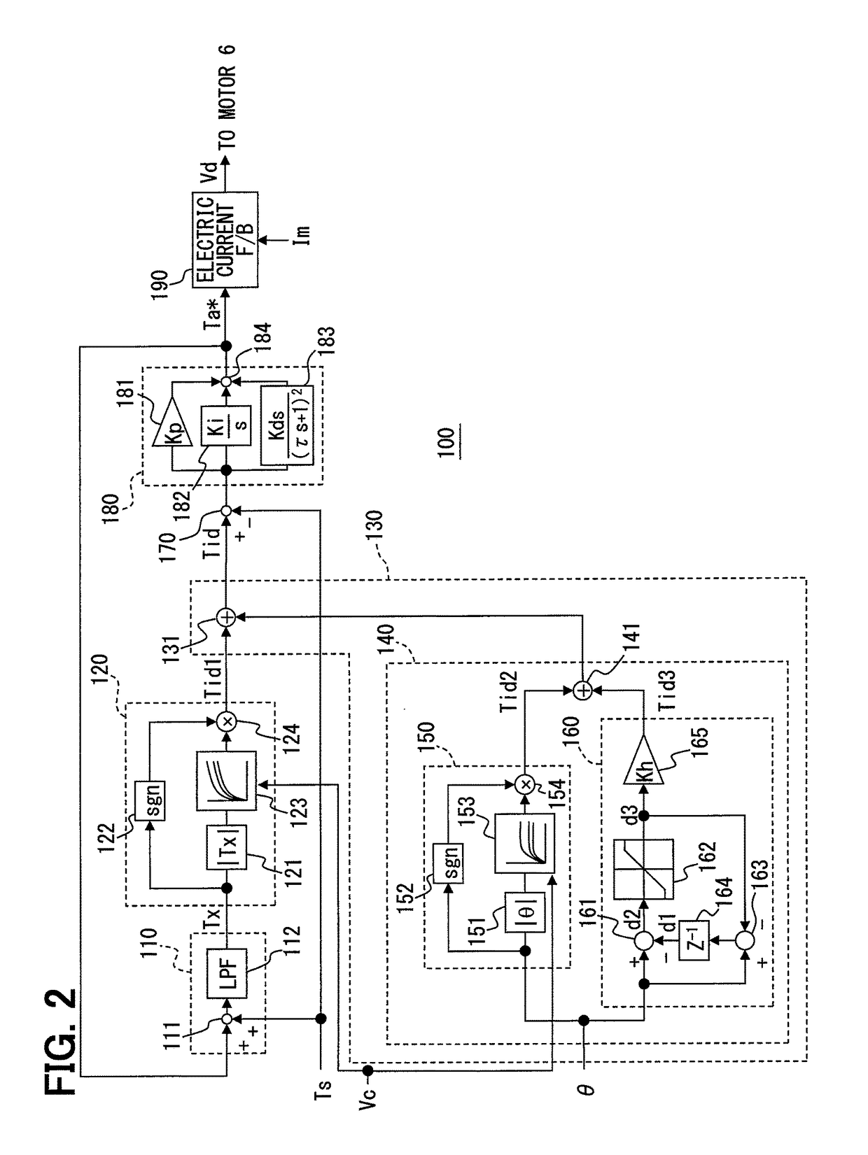
[0112]The electric power steering system of the second embodiment is provided with EPSECU 200 shown in FIG. 9, instead of having EPSECU 100 shown in FIG. 2. The other part of the system is the same as the system 1 in the first embodiment.

[0113]EPSECU 200 is provided with the same components (i.e., the load estimation part 110, the pre-correction target determination part 120, the subtraction part 170, the servo controller 180, and the electric current feedback part 190) that are described in the first embodiment. Further, the target correction part 130 is replaced with a target correction part 230.

[0114]The target correction part 230 is pro...

third embodiment

[0129]The third embodiment of the present disclosure is described in the following. The electric power steering system of the third embodiment has, in place of EPSECU 200 shown in FIG. 9, EPSECU 300 shown in FIG. 12. Other configuration are the same as the electric power steering system of the second embodiment.

[0130]EPSECU 300 has a target correction part 330 that is differently configured from the target correction part 230 of the second embodiment. Other configurations are the same as EPSECU 200 of the second embodiment.

[0131]The target correction part 330 also is provided with the restrictor 233 that is found in the target correction part 230 of the second embodiment. In addition to the above, the target correction part 330 has an adder 338 that is equivalent to a pseudo differentiator 331, an absolute value generator 332, an amplifier 333, the correction amount determination part 334, a pre-correction lower limit determination part 335, a subtracter 336, a pre-correction upper ...


PUM


Abstract

A steering controller for controlling an electric power steering includes a load estimator estimating a road surface load, a pre-correction target determiner determining a pre-correction target steer torque based on the estimated road surface load, a steer angle detector detecting a steer angle, and a target corrector correcting the pre-correction target steer torque based on the steer angle, and the controller determines an assist torque instruction value based on the deviation between the target steer torque and a steer torque, thereby establishing a robust steering feel of an electric power steering system irrespective of the change of the mechanical friction of the power steering system.

Description

CROSS REFERENCE TO RELATED APPLICATION[0001]The present application is based on a Japanese Patent Application No. 2014-078848, filed on Apr. 7, 2014, the disclosure of which is incorporated herein by reference.TECHNICAL FIELD[0002]The present disclosure generally relates to an electric power steering controller for controlling an electric power steering system, which assists a steering operation of a driver in a vehicle by using a motor.BACKGROUND INFORMATION[0003]An electric power steering controller disclosed in a patent document, Japanese Patent Laid-Open No. JP 2013-52793 A (patent document 1) estimates a load of a steering mechanism from a steer torque and from an assist torque instruction value, and sets a target steer torque based on the estimated load. Then, for the matching of the steer torque with the target steer torque, the controller calculates an assist torque instruction value based on a deviation of the steer torque from the target steer torque.[0004]It is generally ...

Claims


Application Information

Patent Timeline
Patent Type & Authority Patents(United States)
IPC IPC(8): B62D15/02B62D6/00B62D5/04
CPCB62D15/025B62D5/0481B62D6/002B62D5/008B62D5/0466
Inventor KATAOKA, MOTOAKIHIRATE, YOSUKE
Owner DENSO CORP
Learn More