
Function execution program, terminal device, function execution method, recording medium and information processing system

a technology of function execution and terminal device, applied in the direction of mechanical pattern conversion, instruments, computing, etc., can solve the problem that the link information displayed around the menu buttons is erroneously selected when the touch panel is opened

Active Publication Date: 2017-06-06
RAKUTEN GRP INC
View PDF12 Cites 5 Cited by
  • Summary
  • Abstract
  • Description
  • Claims
  • Application Information

AI Technical Summary

Benefits of technology

Enhances user convenience by allowing single-action execution of functions without accidental object selection, enabling more intuitive and efficient operation on touch panels.

Problems solved by technology

However, there was a problem that since a display screen on a portable terminal is small and the menu buttons displayed on the first contact are correspondingly small, objects such as link information displayed around the menu buttons are erroneously selected when the touch panel is contacted again.

Method used


Image

  • Function execution program, terminal device, function execution method, recording medium and information processing system
  • Function execution program, terminal device, function execution method, recording medium and information processing system
  • Function execution program, terminal device, function execution method, recording medium and information processing system

Examples


first embodiment

1. First Embodiment

1.1 Outline of Structure and Function of Shopping System

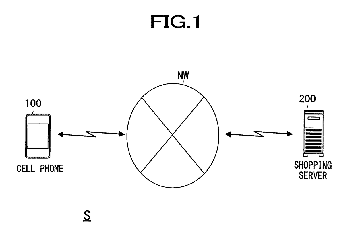
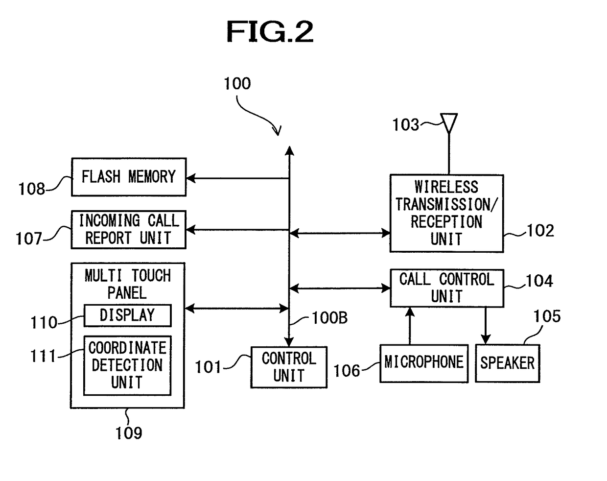
[0064]First, a structure and schematic function of a shopping system S according to the present embodiment will be described with reference to FIG. 1 and FIG. 2.

[0065]FIG. 1 is a diagram showing an example of the schematic structure of the shopping system S according to the present embodiment.

[0066]As shown in FIG. 1, the shopping system S includes a cell phone 100 as an example of a terminal device, and a shopping server 200 as an example of a server device. The shopping server 200 and the cell phone 100 can mutually send and receive data by use of such as TCP / IP or the like as communication protocol via a network NW. Incidentally, the network NW is constructed of, for example, Internet, a dedicated communication line (such as CATV (Community Antenna Television) line), a mobile communication network (including base stations and the like), a gateway, and the like.

[0067]In the thus-configured shopping system S...

second embodiment

2. Second Embodiment

[0113]A second embodiment will be described below. The second embodiment will be described only for different points from the first embodiment, and a detailed explanation of the same points as the first embodiment will be omitted.

[0114]In the first embodiment, the functions are assigned to the slide directions, respectively, in the hold and slide operation. To the contrary, in the second embodiment described later, the functions are assigned to the slide directions and the contact duration.

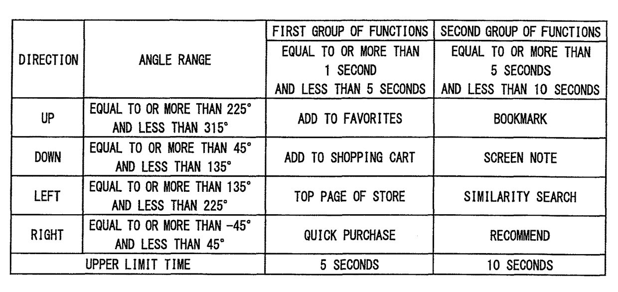
[0115]FIG. 7 is a diagram showing an example of contents set in a function table. In the function table according to the present embodiment, groups of functions are assigned to the ranges of the contact duration, respectively. For example, when the minimum contact time is 1 second, the first group of functions is assigned to the period of equal to or more than 1 second and less than 5 seconds, and the second group of functions is assigned to the period of equal to or more than ...


PUM


Abstract

There are provided a function execution program, a terminal device, a function execution method, a recording medium and an information processing system capable of providing a more convenient touch panel operation method to a user. A computer is caused to function as a time measure means that detects a contact on an input means integral with a display means and measures contact duration at the contact point, a distance measure means that detects a continuous movement of the contact point and measures a moving distance, and an execution means that when the contact duration is a predetermined time or more and the moving distance is a predetermined distance or more, executes a preset function.

Description

CROSS REFERENCE TO RELATED APPLICATIONS[0001]This application is a National Stage of International Application No. PCT / JP2010 / 067880 filed Oct. 12, 2010, claiming priority based on Japanese Patent Application No. 2009-243998, filed Oct. 23, 2009, the contents of all of which are incorporated herein by reference in their entirety.TECHNICAL FIELD[0002]The present invention relates to a technical field of a terminal device comprising a touch panel, a function execution method in the terminal device, and the like.BACKGROUND ART[0003]There has been conventionally used a touch panel configured such that when a user contacts the touch panel, preset menu buttons are displayed in response to the contact point, and when the touch panel is temporarily de-touched (the user separates a finger or the like contacting the touch panel from it) and then the user contacts the menu button again, a predetermined function is executed.[0004]However, there was a problem that since a display screen on a por...

Claims


Application Information

Patent Timeline
Patent Type & Authority Patents(United States)
IPC IPC(8): G06F3/0488G06F3/01G06F3/0482
CPCG06F3/04883G06F3/017G06F3/0488
Inventor TAKAMI, SHINYA
Owner RAKUTEN GRP INC
Learn More