
Telemetry method and system for subsurface well and reservoir and logging data

a technology of subsurface wells and reservoirs, applied in the field of hydrocarbon exploration and production, can solve the problems of limited signal transmission capacity of transmission mediums, large increase in the amount of signal data, and the requirement of signal data per unit of time to exceed the signal carrying capacity (bandwidth) of transmission mediums such as cables, so as to improve communication reliability and communication speed

Active Publication Date: 2017-05-30
BAKER HUGHES INC
View PDF9 Cites 2 Cited by
  • Summary
  • Abstract
  • Description
  • Claims
  • Application Information

AI Technical Summary

Benefits of technology

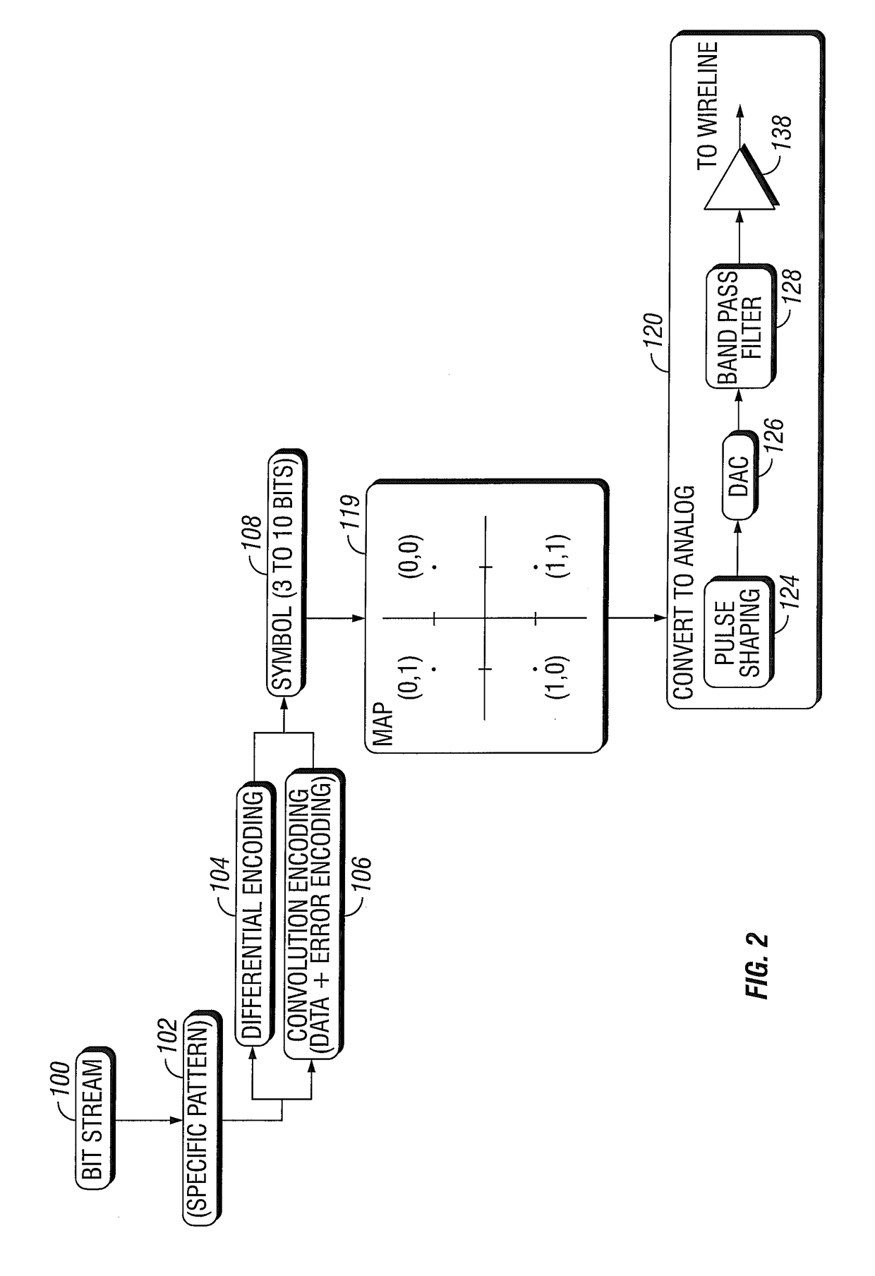
The present invention is about improving communication between devices in oil and gas exploration to enhance communication reliability and speed. It is an adaptable multi-channel signal modulation method that combines the noise-coping capability of the DMT-like method and the digital implementation capability of a CAP-like method with additional novel characteristics beneficial to the targeted applications. This method allows for more efficient data transmission by continuously adapting to the media transmission conditions and utilizing certain ranges of the media's frequency spectrum that provide faster transmission rates. The data rate utilization, compensation, and correction factors of each channel are updated periodically based on the media's characteristics at each channel. This method provides a more robust and flexible data transmission system for oil and gas exploration.

Problems solved by technology

A particular problem in combining large numbers of measurements in the tool string is that the large amount of signal data to be transmitted can cause the required quantity of signal data per unit of time (e.g., bits per second) to exceed the signal carrying capacity (bandwidth) of the transmission medium, such as a cable.
This problem is particularly acute when imaging tools are included in a tool string because of the very fine measurement both in time and space, and consequently the large increase in the amount of signal data, of imaging tools relative to other types of tools.
The cable—indeed, any transmission medium—may have limited signal transmission capacity for any of a number of reasons, some controllable, some not.
A drawback to QAM when used in wireline well logging tool signal telemetry is that precise recovery of the data signal impressed onto the carrier requires a complex and expensive signal demodulator to precisely recover the amplitude and phase of the carrier.
This application has a perceived drawback of wasting the transmission media's power dynamic range available with carrier energy which effectively does not transmit any data.
Each technology has demonstrated operational success bringing certain advantages as mentioned, but as presently defined within the telecommunications industry, the two methods are significantly different and not compatible.
Also, unlike the telecommunications market, the cost of the communication device is of only minor concern.
For example, if the communication method required several additional components, such as DSP's (digital signal processors), the incremental cost would be a minor fraction of the cost of the combined investment in the communication and associated devices employed.
A perceived drawback to CAP systems such as proposed in the Sobrara et al. reference is—that the system is best suited for telecommunications applications (e.g., a public telephone network), rather than for well logging applications.
The system described in the Sobrara et al. reference can have inadequate ability to compensate for changes in signal timing that can particularly occur in wireline signal telemetry because of changes in electrical signal transmission properties of the cable and in signal timing generator changes in the well logging tools.
A possible disadvantage of this method is the vulnerability of a single channel operation.
If this channel becomes corrupted by noise the entire telemetry system is shut down.

Method used


Image

  • Telemetry method and system for subsurface well and reservoir and logging data
  • Telemetry method and system for subsurface well and reservoir and logging data
  • Telemetry method and system for subsurface well and reservoir and logging data

Examples


Embodiment Construction

[0040]In the disclosure that follows, in the interest of clarity, not all features of actual implementations are described. It will of course be appreciated that in the development of any such actual implementation, as in any such project, numerous engineering and technical decisions and selections must be made to achieve specific goals, while operating within the various known constraints that may be posed, which will vary from one implementation to another. Moreover, it is necessary to adhere to proper engineering and development practices for the environment in question. It will be appreciated that such development efforts might be complex and time-consuming, but would nevertheless be a routine undertaking for those of ordinary skill in the relevant fields.

[0041]One implementation of this invention method is described below. As noted above, the invention is directed to the use of a transmission medium having a limited frequency bandwidth. In accordance with one aspect of the inve...


PUM


Abstract

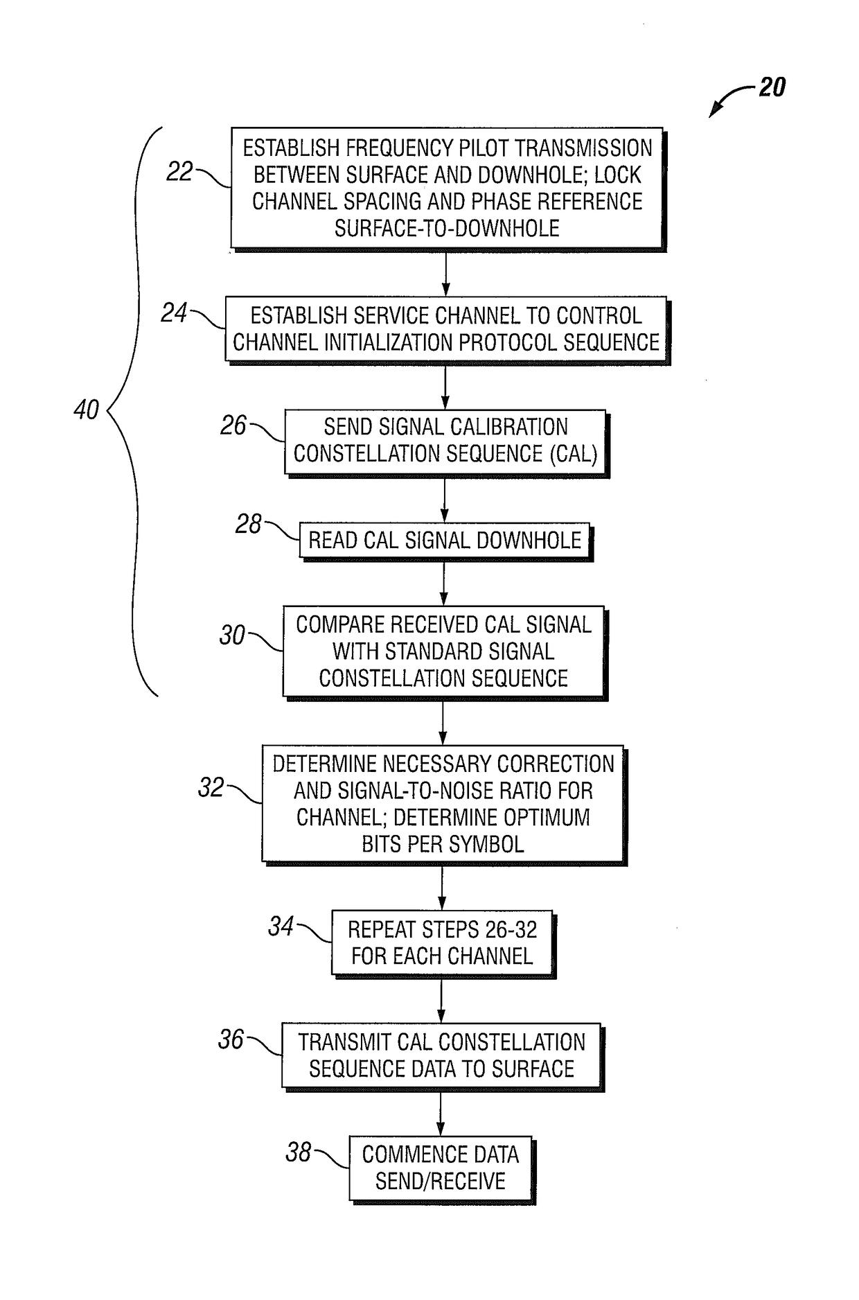
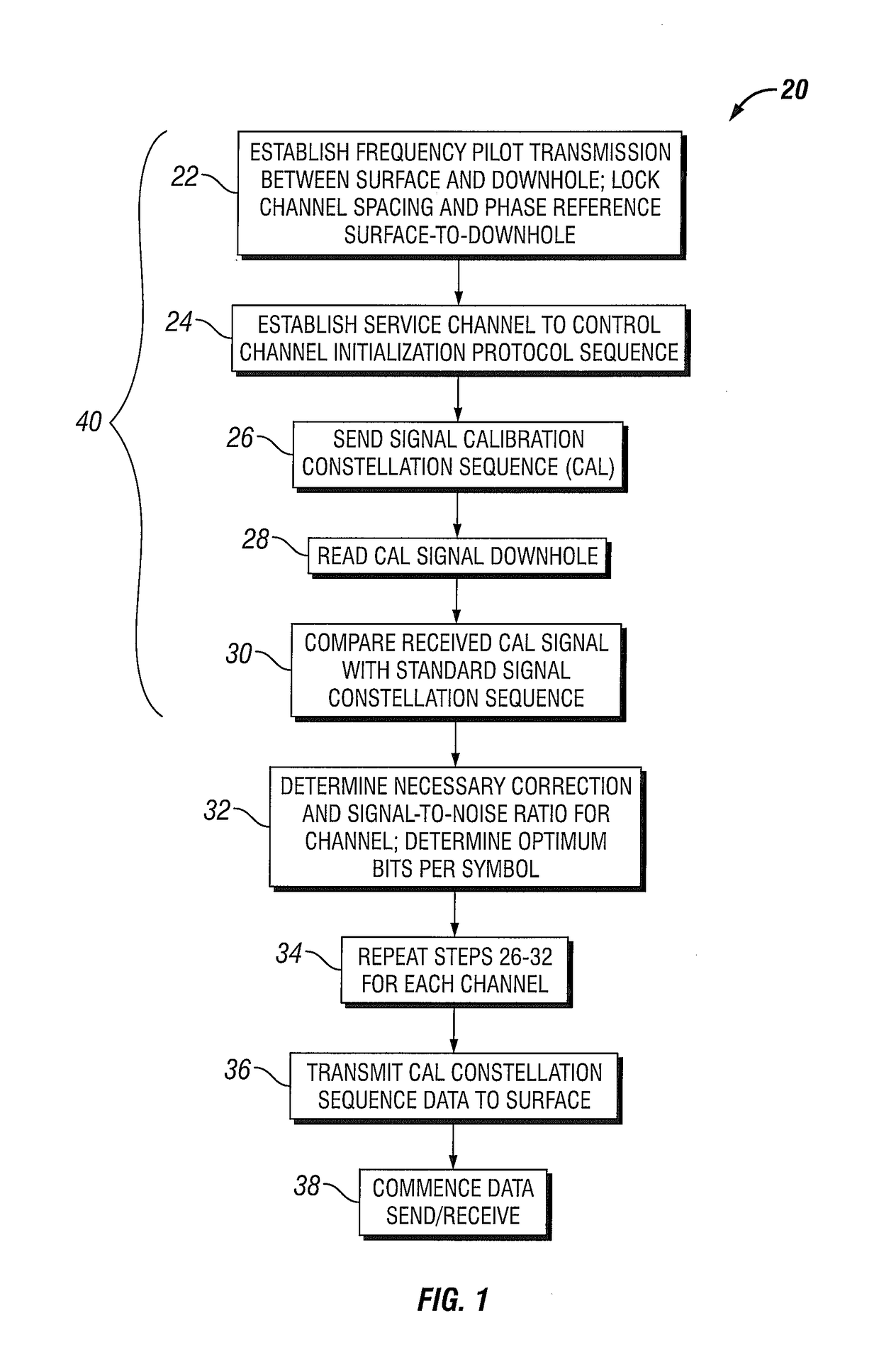
A method and system for transmitting data through a transmission medium in a wellbore. A surface transceiver and a subsurface transceiver are each configured to selectively transmit over a plurality of transmission channels. The surface transceiver is adapted to initialize a channel to determine at least one parameter affecting the current maximum data rate for transmission of information through the channel using a given transmission methodology. At least one of the channels uses carrierless phase / amplitude (CAP) modulation for its transmission methodology. The surface transceiver and the subsurface transceiver adapt to cooperatively periodically test a channel by transmission of a calibration signal from the subsurface transceiver to the surface transceiver. Control circuitry compares the received calibration signal with the calibration signal, responding to the result of the comparison to adjust at least one parameter as necessary to achieve an optimum rate of data transmission through said channel.

Description

FIELD OF THE INVENTION[0001]The present invention relates generally to hydrocarbon exploration and production, and more particularly relates to a method and system for subsurface to surface data transmission.BACKGROUND OF THE INVENTION[0002]The present invention is related to the field of subsurface to surface data transmission involving reservoir management, electric wireline well logging tools, and other subsurface logging devices. More specifically, the present invention is related to systems for communicating data signals (e.g., logging data) from locations disposed deep within wellbores to a surface-based transceiver, such as a recording system or a relay repeater (wireless or other transmission means) located at the earth's surface.[0003]Those of ordinary skill in the art will be quite familiar with the use of electric wireline well logging tools, which are used to make measurements of certain properties of earth formations penetrated by wellbores. The measurements can assist ...

Claims


Application Information

Patent Timeline
Patent Type & Authority Patents(United States)
IPC IPC(8): G01V11/00E21B47/12
CPCG01V11/002E21B47/12G06F17/14
Inventor FANINI, OTTO N.VISWANATHAN, RAMANMAXIT, JORGE OMARANDRADE, HAROLD
Owner BAKER HUGHES INC
Learn More