Method and device for determining reflection coefficients on filter arrangements having thin layers

a filter arrangement and reflection coefficient technology, applied in the direction of immunoassays, component separation, material testing goods, etc., can solve the problems of insufficient sensitivity and reliability of these measurement processes, inability to achieve uniform intensity distribution, and disadvantageous dependence of all conventional methods on intensity, so as to achieve significant reduction of data amount and improve signal quality

Active Publication Date: 2017-05-23
BIOCOPY HLDG AG
View PDF17 Cites 0 Cited by
  • Summary
  • Abstract
  • Description
  • Claims
  • Application Information

AI Technical Summary

Benefits of technology

[0057]The use of CCD arrays is always preferred when the reflected light is to be detected in structured form, so that the light incident on the carrier with the thin layer, preferably in form of individual light sources, can be directly associated individually for the respective illuminated individual spot on the thin layer with the respective spot. This is advantageous in particular with different compounds disposed ...

Problems solved by technology

With this experimental technique, all conventional methods disadvantageously depend appreciably on the intensity.
It was also disadvantageous with respect to the reference measurements for the brightness of the light source that a uniform intensity distribution could not be achieved at least for those measurements to be performed by using so-called multi-well plates.
The sensitivity and reliability of these measurement processes are thus inadequate...

Method used


Image

  • Method and device for determining reflection coefficients on filter arrangements having thin layers
  • Method and device for determining reflection coefficients on filter arrangements having thin layers
  • Method and device for determining reflection coefficients on filter arrangements having thin layers

Examples


Embodiment Construction

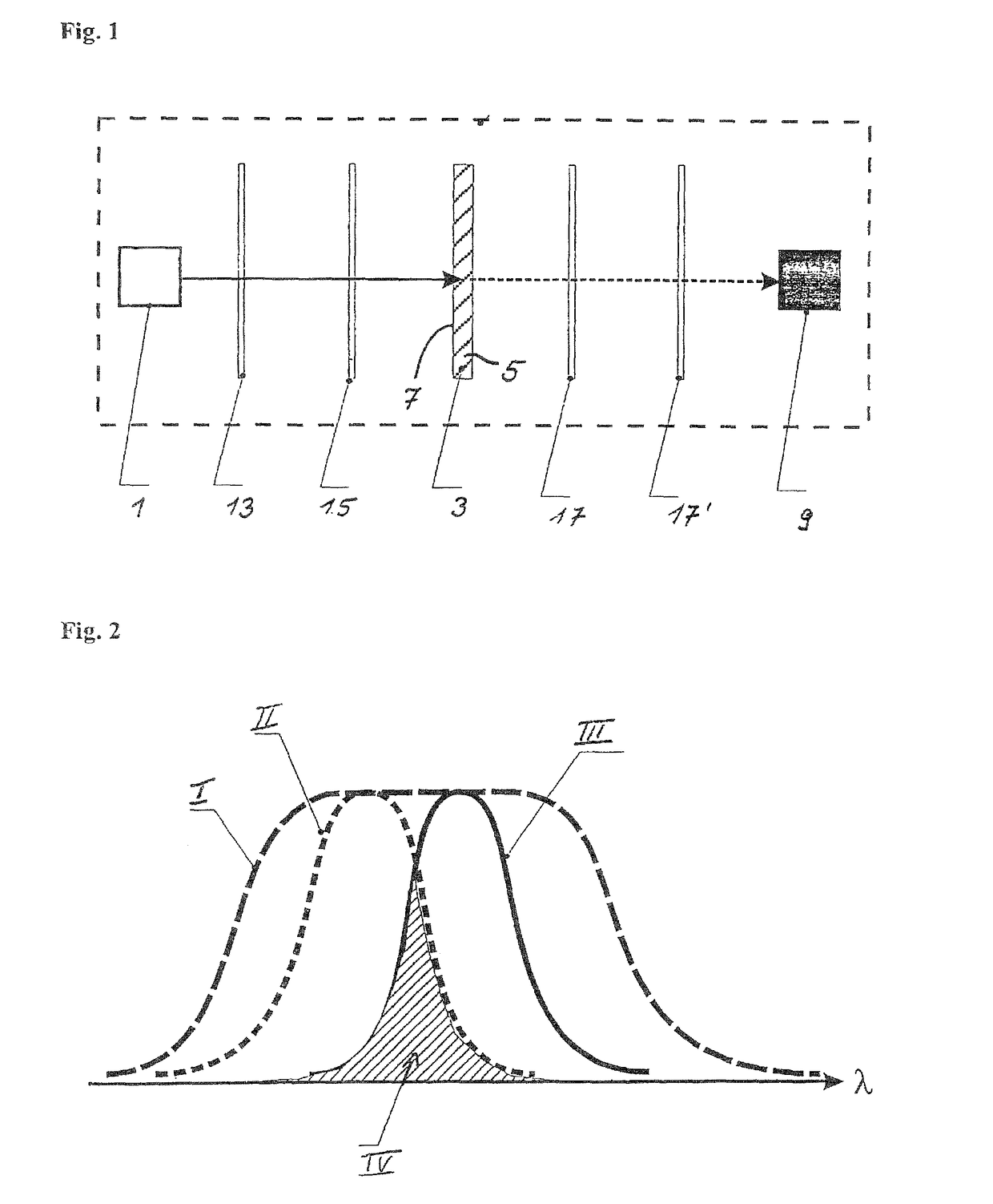
[0077]The reference symbol 1 in FIG. 1 refers to a light source in form of a high-intensity light emitting diode (LED) capable of emitting light in a narrow wavelength range. The light is transmitted directly to the sample, indicated with the overall reference symbol 3, to be tested without using a coupling element, and also without using a collimator for producing a parallel light beam.

[0078]The sample 3 includes an at least partially transparent carrier 5 which in this exemplary embodiment is made of glass in form of an object glass slide and on which a thin layer 7 is applied. For application of this thin layer 13, the designated surface of the carrier 5 is first activated by producing OH-groups on the glass surface.

[0079]The glass surface is now prepared for a surface treatment in form of silanization with epoxy groups, which is in this case performed with an epoxy silane in form of 3-(glycidyl oxypropyl) trimethoxy silane (GOPTS), wherein this is only one of many possible compo...


PUM


Abstract

The invention relates to a method for determining optical properties by measuring intensities on a thin layer, wherein light is irradiated onto a carrier (105) that has said thin layer and that is at least partially transparent. Interferences on the at least one thin layer are measured as the relative intensity of at least one superpositioned wave, optionally using filter arrangements (113, 115, 117) provided for this purpose, whereupon the reflection coefficient(s) and/or the transmission coefficient(s) from the reflection and/or the transmission on the thin layer are determined. Preferably, the intensity of at least two superpositioned waves is measured. The light may be irradiated directly onto the carrier. The invention also relates to a device for determining optical properties by measuring intensities on a thin layer, said device comprising an analysis unit which stores at least one lookup table. The method and the device are preferably used in the area of homeland security.

Description

CROSS-REFERENCES TO RELATED APPLICATIONS[0001]This application is the U.S. National Stage of International Application No. PCT / EP2010 / 002752, filed May 5, 2010, which designated the United States and has been published as International Publication No. WO 2010 / 127843 and which claims the priority of German Patent Application, Serial No. 10 2009 019 711.7, filed May 5, 2009, pursuant to 35 U.S.C. 119(a)-(d).BACKGROUND OF THE INVENTION[0002]The invention relates to a method for determining optical properties by measuring intensities on a thin layer as well as preferred applications, in particular in the area of homeland security.[0003]It is known to determine physical, chemical, biochemical or biological processes, such as reactions, binding and agglomeration processes, and other interactions on a thin layer made of an at least partially optical transparent material by changing the optical layer thickness. For this purpose, light with at least one predetermined selected wavelength is i...

Claims


Application Information

Patent Timeline
IPC IPC(8): G01N21/77G01N21/84G01N21/25G01N21/23G01N21/45G01N21/41
CPCG01N21/8422G01N21/253G01N21/77B01L2200/148G01N21/23G01N21/41G01N21/45Y10S436/805G01N21/455
Inventor LANDGRAF, JOHANNESPROLL, GUNTHERPROLL, FLORIAN
Owner BIOCOPY HLDG AG
Why Eureka
Try Eureka