Pneumatic booster and brake system

a technology of pneumatic booster and brake system, which is applied in the direction of braking system, vehicle components, servomotor components, etc., can solve the problems of increasing invalid pressing force and providing uncomfortable feeling to so as to prevent or reduce the change of brake pressing force, eliminate or reduce the uncomfortable feeling of the driver of the vehicle

Active Publication Date: 2017-05-23
HITACHI ASTEMO LTD
View PDF10 Cites 0 Cited by
  • Summary
  • Abstract
  • Description
  • Claims
  • Application Information

AI Technical Summary

Benefits of technology

[0005]Therefore, if no idling is encouraged for the purpose of reducing an amount of fuel consumed by the engine, the pressure in the constant pressure chamber of the pneumatic booster when the vehicle is stopped is easily placed into a low negative pressure state close to the atmospheric pressure. Further, some vehicles are structurally designed in such a manner that the pressure in the constant pressure chamber of the pneumatic booster is easily placed into a low negative pressure state close to the atmospheric pressure for the reason of improving fuel efficiency or the like, depending on the vehicle. As a result, when the spring force of the return spring is set based on a relatively high negative pressure state, this leads to an increase in an invalid pressing force when a braking operation is performed immediately after the vehicle starts running.
[0007]The present invention has been contrived in consideration of the above-described drawback of the conventional technique, and an object of the present invention is to provide a pneumatic booster and a brake system that allow a weak force to be set as a spring force of a biasing member, and can prevent or reduce a change in a brake pressing force when a braking operation is performed to thereby eliminate or reduce an uncomfortable feeling of a driver of a vehicle.
[0012]According to the present invention, it is possible to set a weak force as the spring force of the biasing member for returning the valve body to the variable pressure chamber side when a braking operation is released, and prevent or reduce a change in a brake pressing force when a braking operation is performed to eliminate or reduce an uncomfortable feeling of a driver of the vehicle.

Problems solved by technology

As a result, when the spring force of the return spring is set based on a relatively high negative pressure state, this leads to an increase in an invalid pressing force when a braking operation is performed immediately after the vehicle starts running.
These vehicles involve such a drawback that a brake pressing force is changed every time the pressure in the constant pressure chamber of the pneumatic booster is placed into a low negative pressure state, whereby an uncomfortable feeling is provided to a driver of the vehicle.

Method used


Image

  • Pneumatic booster and brake system
  • Pneumatic booster and brake system
  • Pneumatic booster and brake system

Examples


first embodiment

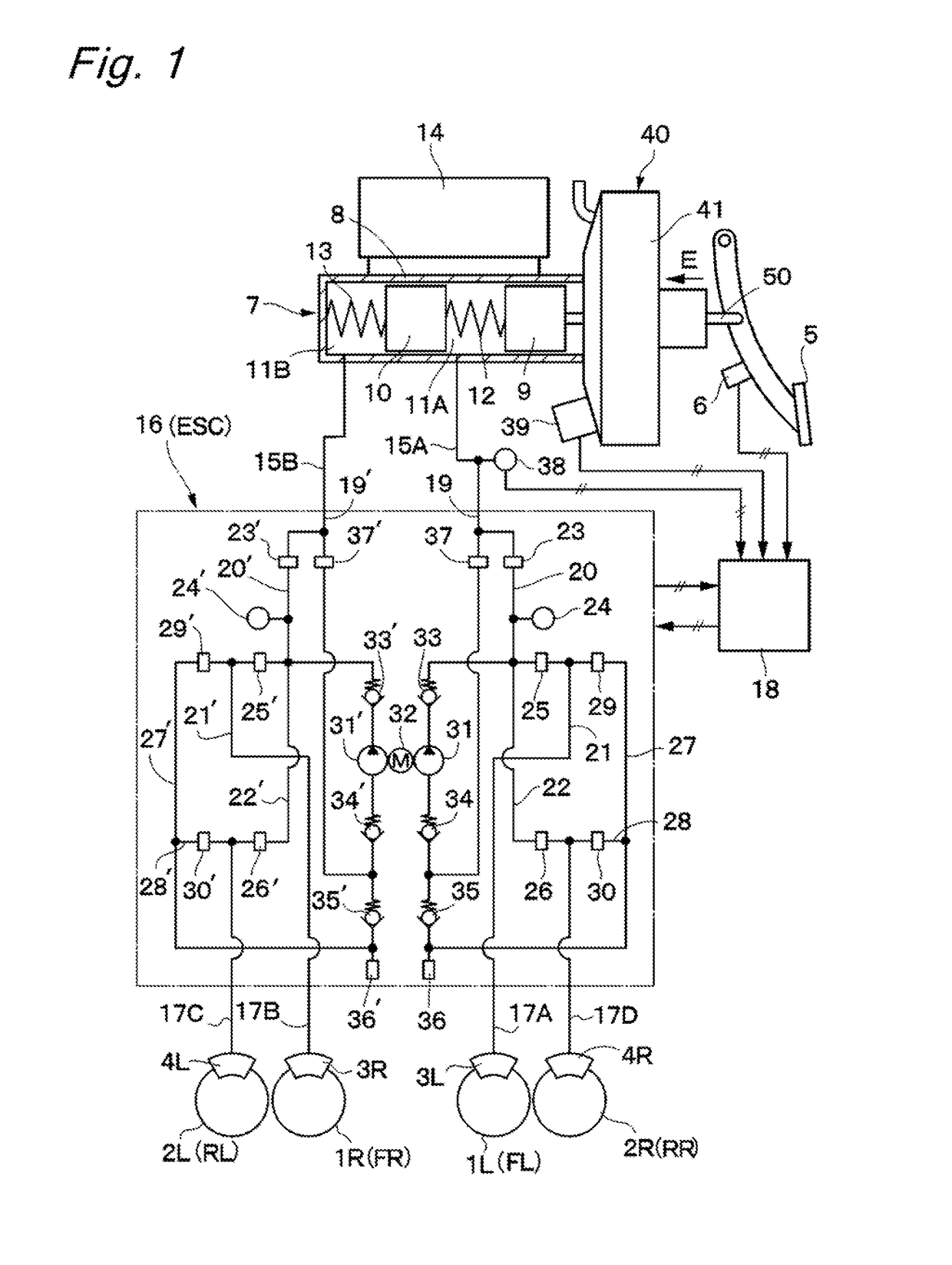
[0021]FIGS. 1 to 4 illustrate the present invention. In FIG. 1, front left and right wheels 1L and 1R, and rear left and right wheels 2L and 2R are mounted under a vehicle body (not illustrated), which constitutes a main structure of a vehicle. Front wheel-side wheel cylinders 3L and 3R are mounted on the front left and right wheels 1L and 1R, respectively, and rear wheel-side wheel cylinders 4L and 4R are mounted on the rear left and right wheels 2L and 2R, respectively. These wheel cylinders 3L, 3R, 4L and 4R constitute cylinders of hydraulic disk brakes or drum brakes, and function to apply braking forces to the respective wheels (the front wheels 1L and 1R, and the rear wheels 2L and 2R) for each wheel.

[0022]A brake pedal 5 is mounted on a front board side of the vehicle body, and this brake pedal 5 is pressed by a driver when the driver brakes the vehicle. A stroke sensor 6 is mounted on the brake pedal 5. This stroke sensor 6 detects an amount of a pressing operation performed...

fourth embodiment

[0115]In FIG. 7, reference numeral 91 denotes a bellows-like cylindrical body as a cylindrical member employed in the fourth embodiment, and the bellows-like cylindrical body 91 is formed as an expandable and shrinkable boot made from an elastic resin material and has both axial end sides formed as thick annular attachment portions 91A and 91B. The annular attachment portion 91A on a one axial side is formed so as to have a smaller diameter than the annular attachment portion 91B on an opposite axial side, and have a generally equal radial dimension to the dimension of the cylindrical protruding portion 46D of the valve body 46. The annular attachment portion 91A of the bellows-like cylindrical body 91 is fixed to the cylindrical protruding portion 46D of the valve body 46 with use of a fixation piece 93, which will be described below, so as to be prevented from being detached off.

[0116]On the other hand, the annular attachment portion 91B of the bellow-like cylindrical body 91 is f...


PUM


Abstract

A pneumatic booster (40) disposed between a brake pedal (5) and a master cylinder (7) includes a cylindrical member (60) provided on an outer circumferential side of an output rod (58). A seal member (62) seals between an outer circumferential side of the cylindrical member and a cylindrical portion of a front shell, and an O-ring seals between the cylindrical member and the output rod. The cylindrical member causes a differential pressure between a negative pressure chamber (A) and an atmosphere chamber (C) to be applied to a valve body (46). One axial side of the cylindrical member is configured to cause an atmosphere pressure to be applied to the valve body by abutting against a cylindrical protruding portion of the valve body, thereby pushing the valve body with the aid of the differential pressure in the direction as a biasing direction of a return spring.

Description

TECHNICAL FIELD[0001]The present invention relates to a pneumatic booster used as, for example, a negative pressure booster of a brake system for a vehicle, and a brake system with the pneumatic booster employed therefor.BACKGROUND ART[0002]Generally, a brake system of a vehicle includes a pneumatic booster disposed between a brake pedal and a master cylinder. This type of pneumatic booster boosts a pressing force applied from the brake pedal to an input rod according to a pressure difference between a constant pressure chamber and a variable pressure chamber inside the pneumatic booster. By this operation, the pneumatic booster is configured to transmit a large output from an output rod to the master cylinder side. The constant pressure chamber (i.e., a negative pressure chamber) of the pneumatic booster is connected to an intake manifold of an engine for the vehicle, and the constant pressure chamber is set into a lower pressure state than an atmospheric pressure with the aid of a...

Claims


Application Information

Patent Timeline
Patent Type & Authority Patents(United States)
IPC IPC(8): B60T13/24F15B13/02B60T13/52B60T13/57
CPCB60T13/241B60T13/52B60T13/57F15B13/021
Inventor ENDO, MITSUHIROWATANABE, SHUZO
Owner HITACHI ASTEMO LTD
Why Eureka
Try Eureka