Charging system including a battery pack that outputs a stop request signal and a charging apparatus that stops power conversion in receipt of the stop request signal

a charging system and stop request technology, applied in the direction of electric programme control, program control, instruments, etc., can solve the problems of no way to monitor the control state of the microcomputer inside the battery pack, and anomaly cannot be detected

Active Publication Date: 2017-05-09
MAKITA CORP
View PDF18 Cites 0 Cited by
  • Summary
  • Abstract
  • Description
  • Claims
  • Application Information

AI Technical Summary

Benefits of technology

[0050]In the charging control device configured as such, when the operation state of the control unit inside the charging apparatus is the specified operation state, the charging power outputted from the charging apparatus can be interrupted in the battery pack side by outputting the stop request signal to the battery pack from the charging apparatus. Thereby possibility that a trouble may occur to the rechargeable battery can be reduced.

Problems solved by technology

Accordingly, even if some anomaly occurs to the microcomputer inside the charger, for example, in a state where the rechargeable battery is still connected after being charged, the anomaly cannot be detected.
If anomaly occurs to the microcomputer in such state, the anomaly cannot be detected.
In addition, there is no way to monitor the control state of the microcomputer inside the battery pack.

Method used


Image

  • Charging system including a battery pack that outputs a stop request signal and a charging apparatus that stops power conversion in receipt of the stop request signal
  • Charging system including a battery pack that outputs a stop request signal and a charging apparatus that stops power conversion in receipt of the stop request signal
  • Charging system including a battery pack that outputs a stop request signal and a charging apparatus that stops power conversion in receipt of the stop request signal

Examples


first embodiment

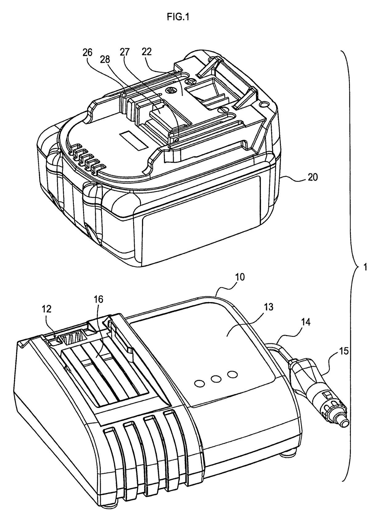
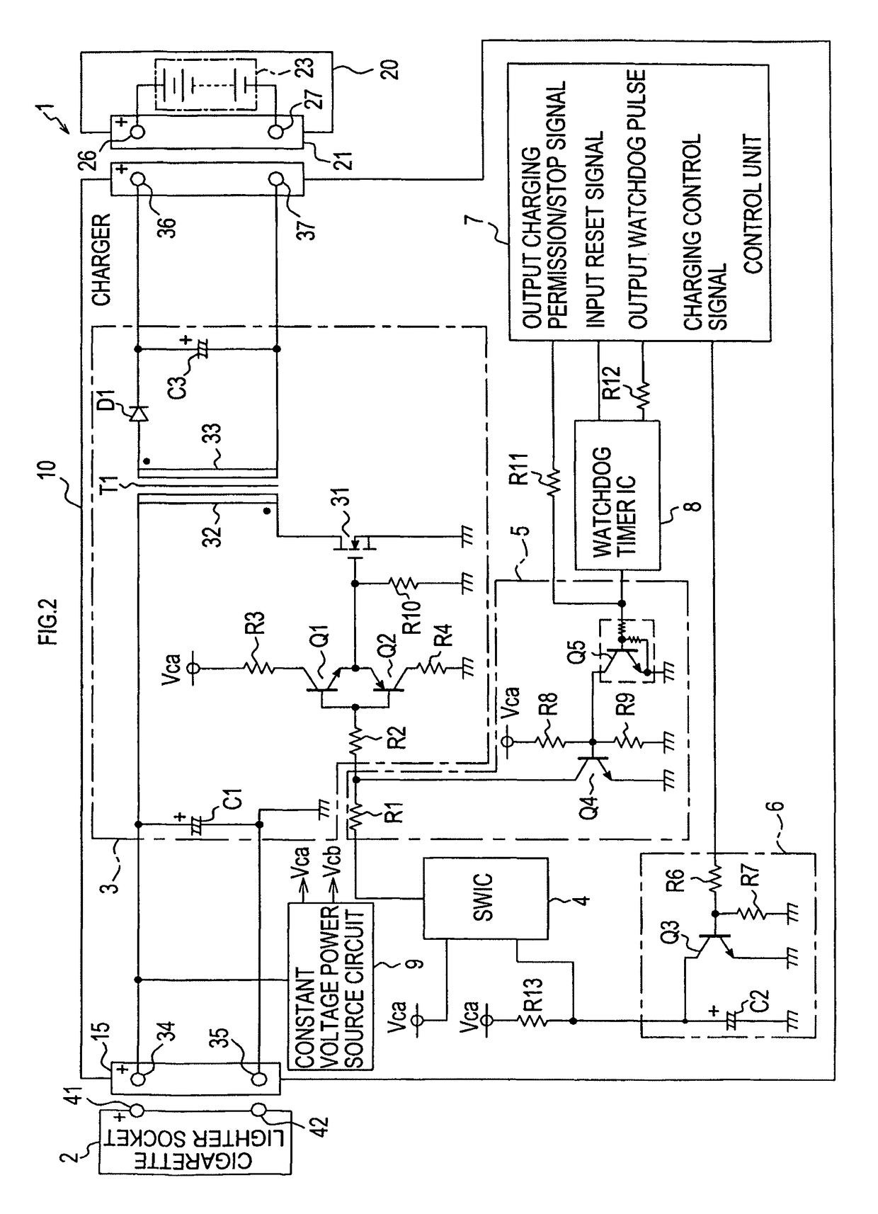
[0069]A charging system 1 of the present embodiment shown in FIGS. 1 and 2 includes a charger 10 and a battery pack 20 for charging a battery (rechargeable battery) used as a power source, for example, of an electric power tool. The system is configured to charge a rechargeable battery inside the battery pack 20 by the charger 10.

[0070]The charger 10 generates a charging power which is a direct-current power for charging the rechargeable battery inside the battery pack 20 from a direct-current power from a cigarette lighter socket 2 (see FIG. 2) provided in a not shown vehicle. A voltage of the direct-current power generated by the charger 10 of the present embodiment may not be strictly constant and include a pulsating flow component. More particularly, the charger 10 includes a cigarette lighter plug 15 to be connected to the cigarette lighter socket 2 for inputting a direct-current power from the battery of the vehicle into the charger 10. When the cigarette lighter plug 15 is in...

second embodiment

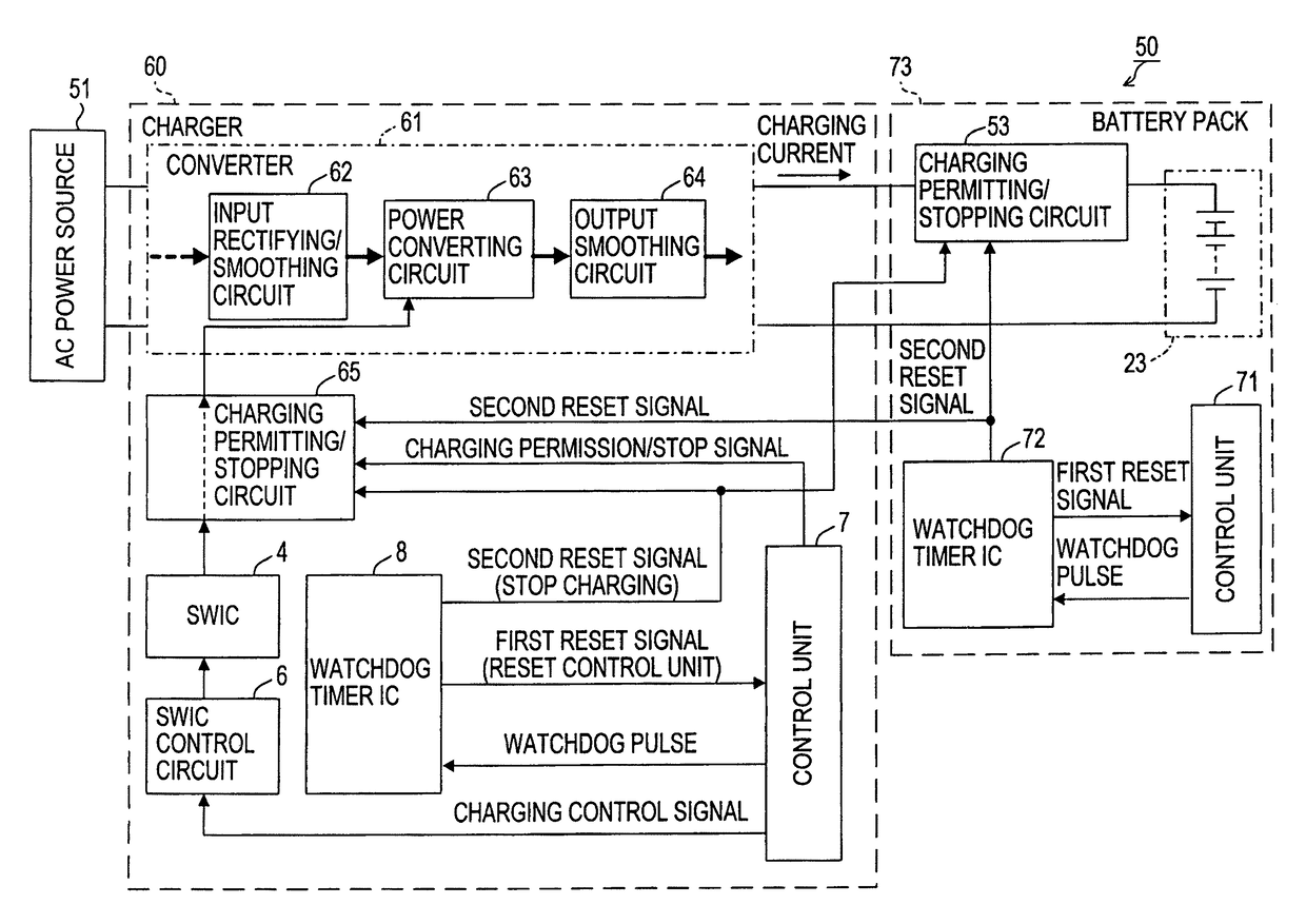
[0136]Now, a charging system according to a second embodiment will be explained by way of FIG. 6. A charging system 50 of the present embodiment is different from the charging system 1 of the first embodiment in that the supply source of the external power inputted to a charger 60 is an alternating-current power source 51 in the present embodiment. Thus, a converter 61 of the charger 60 includes: an input rectifying / smoothing circuit 62 that rectifies an alternating-current power from the alternating-current power source 51 to be converted to a direct-current power; a power converting circuit 63 that converts the direct-current power from the input rectifying / smoothing circuit 62 to an alternating-current power having a predetermined alternating-current voltage; and an output smoothing circuit 64 that smoothes the alternating-current power converted by the power converting circuit 63 to generate a charging power.

[0137]The power converting circuit 63 is identical to the portion in FI...


PUM


Abstract

A charging control device includes a control unit and a monitoring unit. The control unit performs at least one of controlling charging to a rechargeable battery and monitoring a state of a rechargeable battery, while outputting a state signal which indicates an operation state of the control unit. The monitoring unit determines whether or not the operation state of the control unit is a predesignated specified operation state based on the state signal outputted from the control unit.

Description

CROSS-REFERENCE TO RELATED APPLICATIONS[0001]This application is a Continuation of application Ser. No. 12 / 385,550, which claims the benefit of Japanese Patent Application No. 2008-105775 filed Apr. 15, 2008 in the Japan Patent Office, the disclosures of which are incorporated herein by reference.BACKGROUND[0002]The present invention relates to a charging control of a rechargeable battery.[0003]In recent years, a charger provided with a microcomputer for the purpose of achieving high functionality and efficiency is widely used as a charger for charging various rechargeable batteries such as a nickel hydride rechargeable battery and a lithium ion rechargeable battery. In the charger, the microcomputer controls battery charging based on various information inside the charger and also from a battery pack including a rechargeable battery.[0004]Not only the charger but also the battery pack including a rechargeable battery is now being widely used which is provided with a microcomputer a...

Claims


Application Information

Patent Timeline
Patent Type & Authority Patents(United States)
IPC IPC(8): H02J7/00H02J7/02G05B19/042G05B19/05G06F11/07
CPCH02J7/007G05B19/0428G05B19/058G06F11/076G06F11/0757H02J7/0021H02J7/0029H02J7/0047H02J7/0093H02J7/027G05B2219/14086G05B2219/24125G05B2219/25158H02J7/00711H02J7/0049H02H7/18
Inventor MORI, TATSUKIYAMADA, TORUHIRA, SHINICHISUZUKI, HITOSHI
Owner MAKITA CORP
Why Eureka
Try Eureka