
System, devices and methods for measuring differential and absolute pressure utilizing two MEMS sense elements

a technology of differential and absolute pressure and mems sense element, which is applied in the direction of machines/engines, electrical control, instruments, etc., can solve the problems of inherent error in mass flow calculation, and achieve the effect of reducing the oxygen concentration of the air going, reducing the temperature of the intake air, and reducing nox

Active Publication Date: 2017-05-02
SENSATA TECHNOLOGIES INC
View PDF37 Cites 11 Cited by
  • Summary
  • Abstract
  • Description
  • Claims
  • Application Information

AI Technical Summary

Benefits of technology

The present invention solves the problem of sensor inaccuracies caused by sensor spacing and media connection variation by combining an absolute and differential sensor into one package. This minimizes compound errors and reduces contamination accumulation. Additionally, the invention includes a feature to orient the media isolating diaphragms horizontally, which further reduces contamination accumulation and improves accuracy of mass flow calculations. The invention also addresses the issue of exhaust gas recirculation systems by incorporating a part of the exhaust gas after being cooled into the intake side of the engine to lower the oxygen concentration and temperature of the intake air, thereby reducing NOx.

Problems solved by technology

Both of these configurations lead to inherent error in the mass flow calculation by compounding the errors between the two sensors.

Method used


Image

  • System, devices and methods for measuring differential and absolute pressure utilizing two MEMS sense elements
  • System, devices and methods for measuring differential and absolute pressure utilizing two MEMS sense elements
  • System, devices and methods for measuring differential and absolute pressure utilizing two MEMS sense elements

Examples


Embodiment Construction

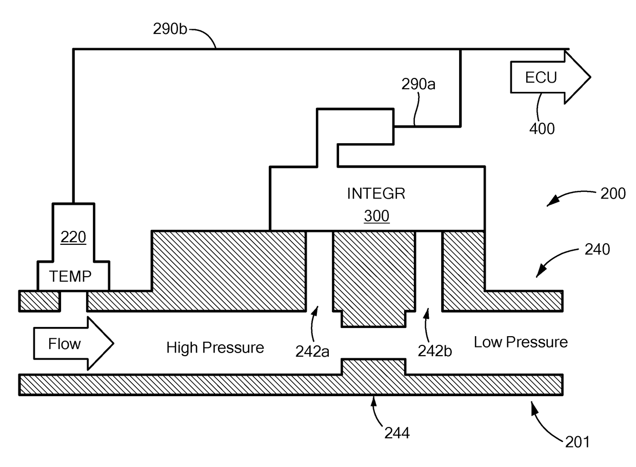
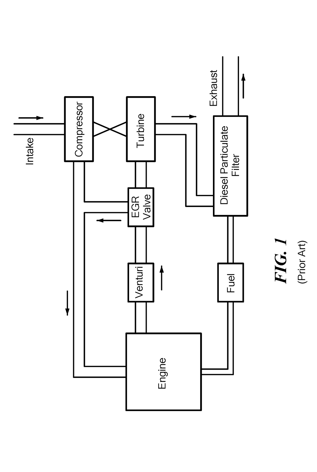
[0091]Referring now to the various figures of the drawing wherein like reference characters refer to like parts, there is shown in FIG. 3 a schematic block diagram view of an exemplary integrated exhaust gas recirculation (EGR) sensing system 200 according to the present invention. Such an EGR sensing system 200 can be located in any EGR system or EGR loop as is known to those skilled in the art such as that shown, for example, in FIG. 1 by appropriate adaptation of the EGR system.

[0092]For example, the fluid system or fluid system piping (e.g., EGR piping 240) in which the EGR sensing system 200 is disposed in can be configured and arranged so as to embody the necessary pressure taps or ports 242 a, b so that the EGR sensing system can be appropriately coupled thereto. Alternatively, the fluid system piping can be configured and arranged so as to include a piping section 201, a piping portion or a piping component that are respectively fluidly coupled to the remaining fluid system ...


PUM


Abstract

Featured are systems and methods for measuring differential and absolute pressure of a flowing fluid / gas in a fluid system. In such a method the fluid system is configured with first and second pressure taps that are spaced from each so the second pressure tap is downstream of the first pressure tap in a direction of flow. An absolute pressure sense element and a differential pressure sense element are provided, where the absolute pressure sense element is first fluidly coupled to one of the first or second pressure tap to measure an absolute pressure representative of the flowing fluid / gas. The differential pressure sense element is second fluidly coupled to each of the first and second pressure taps so as to measure a differential pressure of the flowing fluid / gas between the first and second pressure taps.

Description

FIELD OF INVENTION[0001]The present invention relates to systems, apparatus, devices and methods for measuring differential and absolute pressure. More particularly, the present invention relates to such systems, apparatus, devices and methods that utilize two MEMS sense elements and an oil filed pressure sensor(s). Yet more particularly, the present invention relates to such systems, apparatus, devices and methods that are utilized in combination with a temperature sense element to measure mass flow rate. More specifically, the present invention relates to such systems, apparatus, devices and methods that can be utilized for detecting a pressure and / or flow rate inside an EGR pipe in an EGR system as well as for detecting a pressure and / or flow rate in an intake of an internal combustion engine (e.g., diesel, natural gas).BACKGROUND OF THE INVENTION[0002]In the automotive industry, numerous efforts have been undertaken over the years to restrict or reduce emissions resulting from t...

Claims


Application Information

Patent Timeline
Patent Type & Authority Patents(United States)
IPC IPC(8): G01F1/38F02M26/47G01F1/88
CPCG01F1/88F02M26/47G01F1/86G01L13/00G01L15/00F02D41/0072F02D2041/0075F02D2200/0406G01L13/06G01L19/0645G01L23/24B81B3/0018B81B2201/0264G01L13/025G01L19/147G01L19/148
Inventor ZUMMO, PETERBENDER, VICTOR
Owner SENSATA TECHNOLOGIES INC
Learn More