Control system for a power amplifier

a power amplifier and control system technology, applied in the direction of amplifier modification, amplifier modification to reduce non-linear distortion, amplifiers, etc., can solve the problems of long calibration procedure, which can take up to 48 hrs, and achieve the effect of reducing the measured power of the error signal

Active Publication Date: 2017-04-25
ASTRIUM GMBH
View PDF21 Cites 2 Cited by
  • Summary
  • Abstract
  • Description
  • Claims
  • Application Information

AI Technical Summary

Benefits of technology

[0013]The processing means may be configured to control the phase control means in order to minimise the measured power of the error signal.

Problems solved by technology

However, a drawback of this approach is the lengthy calibration procedure, which can take up to 48 hrs.

Method used


Image

  • Control system for a power amplifier
  • Control system for a power amplifier
  • Control system for a power amplifier

Examples


Embodiment Construction

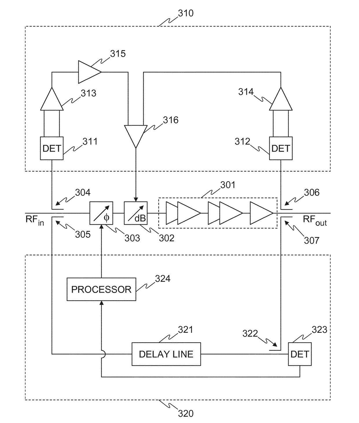
[0034]Referring now to FIG. 2, a system for controlling the gain and phase of an input signal of a power amplifier is illustrated, according to an embodiment of the present invention. The system comprises a power amplifier 201, a gain control module 202, a phase control module 203, a gain control loop 210 for controlling the gain control module 202, and a phase control loop 220 for controlling the phase control module 203. The gain control module 202 may, for example, be a variable attenuator such as the one shown in FIG. 1, and the phase control module 203 may, for example, be a phase shifter such as the one shown in FIG. 1. The gain control module 202 and phase control module 203 can be controlled to change the gain and phase, respectively, of the input RF signal (RFIN) before it is input to the power amplifier 201. Although in FIG. 2 the RFIN signal is input to the phase control module 203 before the gain control module 202, in other embodiments the order of the phase control and...


PUM


Abstract

An apparatus for controlling the gain and phase of an input signal input to a power amplifier comprises a gain control loop configured to control the gain of the input signal based on power levels of the input signal and an amplified signal output by the power amplifier, to obtain a predetermined gain of the amplified signal, and a phase control loop configured to obtain an error signal related to a phase difference between a first signal derived from the input and a second signal derived from the amplified signal, and control the phase based on the error signal, to obtain a predetermined phase of the amplified signal. The phase control loop delays the first signal, such that the delayed first signal and the second signal used to obtain the error signal correspond to the same part of the input signal. The apparatus may be included in a satellite.

Description

RELATED APPLICATIONS[0001]This application is a 35 U.S.C. §371 national stage application of International Application No. PCT / EP2012 / 067779, filed Sep. 12, 2012, which claims the benefit of European Patent Application No. 11275122.7, filed Oct. 10, 2011. The entire contents of each of the foregoing applications are explicitly incorporated herein by reference.FIELD OF THE INVENTION[0002]The present invention relates to a control system for a power amplifier. In particular, the present invention relates to a control system which controls a power amplifier based on an error signal related to a phase difference between a delayed first signal derived from an input signal and a second signal derived from an amplified signal.BACKGROUND OF THE INVENTION[0003]Power amplifiers are used in communications satellites to amplify RF signals. Such power amplifiers are known to exhibit nonlinearity, whereby the gain and phase of the amplified output RF signal varies nonlinearly with the input signa...

Claims


Application Information

Patent Timeline
Patent Type & Authority Patents(United States)
IPC IPC(8): H03F1/26H03G1/00H03F1/34H03F3/19H03F3/21H03F1/32
CPCH03G1/0017H03F1/3247H03F1/3282H03F1/345H03F3/19H03F3/21H03F1/3241H03F2200/405H03F2200/438H03F2200/451H03F2200/66H03F2201/3233H03F1/3223H03F2200/105H03F2200/153H03F2200/228H03F2200/393H03F2200/465H03F2200/78H03F2201/3227H03F2201/3231H03F1/00H03F1/32H03F1/0222H03F2200/102H03G1/0005H03G3/001
Inventor GOSS, MARTIN
Owner ASTRIUM GMBH
Why Eureka
Try Eureka