
Circuits and methods of implementing time-average-frequency direct period synthesizer on programmable logic chip and driving applications using the same

a technology of programmable logic chip and time-average-frequency direct period synthesizer, which is applied in the direction of generating/distributing signals, pulse techniques, instruments, etc., can solve the problems of unpredictable time delay in fpga and the speed that the time scale can be switched, and achieve the effect of expanding people's ability to design electronic systems and powering frequency generation capabilities

Active Publication Date: 2017-04-11
XIU LIMING
View PDF24 Cites 154 Cited by
  • Summary
  • Abstract
  • Description
  • Claims
  • Application Information

AI Technical Summary

Benefits of technology

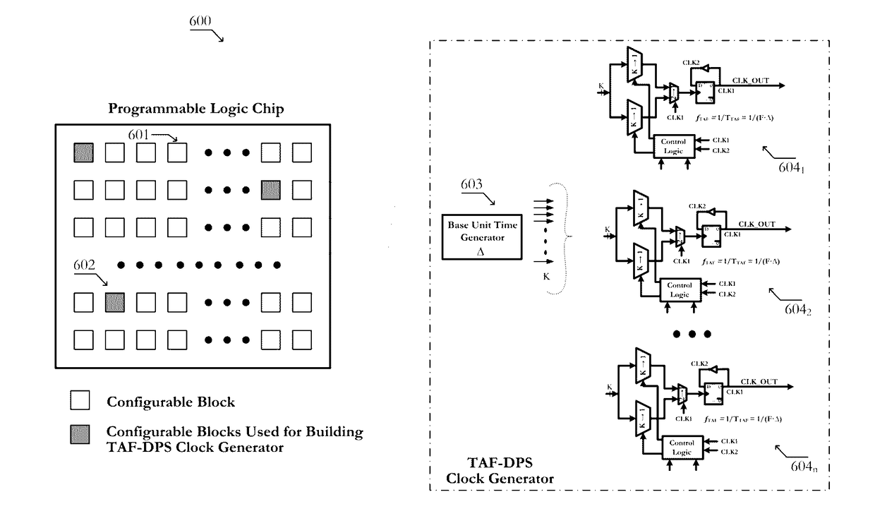
The present invention relates to using programmable logic chip to create clock generators that can be used to drive other functional circuitries on the chip. This allows for the exploration of novel system / architecture / chip level design ideas. The invention takes advantage of the highly flexible TAF-DPS technology and the programmable logic chip's powerful frequency generation capabilities. This advancement expands the capability of designing electronic systems to a higher level.

Problems solved by technology

In addition, another issue is also important: the speed that the time scale can be switched from one to another (the speed of clock frequency switching).
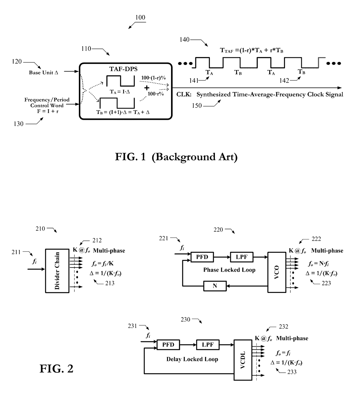
Regardless the tremendous effort spent on the study of frequency synthesis, however, there are still two problems that have not been solved to our complete satisfaction: arbitrary frequency generation (small frequency granularity or fine frequency resolution) and instantaneous frequency switching (fast frequency switching speed).
The time delay in FPGA is unpredictable because of its architecture.

Method used


Image

  • Circuits and methods of implementing time-average-frequency direct period synthesizer on programmable logic chip and driving applications using the same
  • Circuits and methods of implementing time-average-frequency direct period synthesizer on programmable logic chip and driving applications using the same
  • Circuits and methods of implementing time-average-frequency direct period synthesizer on programmable logic chip and driving applications using the same

Examples


Embodiment Construction

[0027]Reference will now be made in detail to various embodiments of the invention, examples of which are illustrated in the accompanying drawings. While the invention will be described in conjunction with the following embodiments, it will be understood that they are not intended to limit the invention to these embodiments. On the contrary, the invention is intended to cover alternatives, modifications and equivalents, which may be included within the spirit and scope of the invention as defined by the appended claims. Furthermore, in the following detailed description, numerous specific details are set forth in order to provide a thorough understanding of the present invention. However, it will be readily apparent to one skilled in the art that the present invention may be practiced without these specific details. In other instances, well-known methods, procedures, components, and circuits have not been described in detail so as not to unnecessarily obscure aspects of the present ...


PUM


Abstract

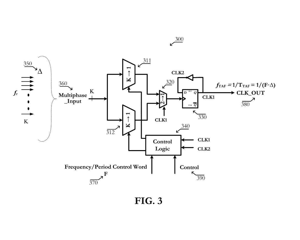
Circuits of a TAF-DPS clock generator implemented on programmable logic chip comprise: 1) a base time unit generator created from configurable blocks, or on-chip PLL, or on-chip DLL, said base time unit generator produces a plurality of phase-evenly-spaced-signals; 2) a TAF-DPS frequency synthesizer created by configuring configurable blocks of said programmable logic chip, said TAF-DPS frequency synthesizer takes said plurality of phase-evenly-spaced-signals as its input. Methods of creating flexible clock signal to drive application comprise: 1) selecting one or more strategic areas in said programmable logic chip; 2) creating one or more TAF-DPS clock generator for each said area by using the configurable resource in said area; 3) creating control function to control the frequency and duty-cycle of the TAF-DPS clock generator output, said control function can be circuit created from configuring configurable blocks, said control function can also be achieved by software; 4) driving the circuits in application by the flexible clock generated from said TAF-DPS clock generator.

Description

FIELD OF THE INVENTION[0001]The present invention generally relates to the field of integrated circuit. More specifically, embodiments of the present invention pertain to circuits and methods of implementing a type of frequency synthesis circuit, Time-Average-Frequency Direct Period Synthesis (TAF-DPS), on programmable logic chip such as FPGA (Field Programmable Gate Array) and CPLD (Complex Programmable Logic Device).DISCUSSION OF THE BACKGROUND[0002]In a typical VLSI system, there are millions of electrical signals. They are used to make the system perform what it is designed to do. Among those, the most important one is the clock signal. From an operational perspective, clock is the timekeeper of the electrical world inside the chip. From a structural perspective, clock generator is the heart of the chip; clock signal is the blood; and clock distribution network is the vessel.[0003]The purpose of a VLSI system is for processing information. The efficiency of performing this task ...

Claims


Application Information

Patent Timeline
IPC IPC(8): G06F17/50G06F1/10H03L7/197H03K19/173H03K19/017H03K19/018G06F1/12H03L7/099H03K19/0185H03K19/096
CPCH03L7/197G06F17/5054H03K19/1737H03L7/0991G06F1/10H03K19/01855H03K19/01728G06F1/12G06F17/5045G06F17/505H03K19/096H03L7/18H03L7/0812H03L7/16G06F30/34G06F30/30G06F30/327G06F2119/12G06F30/343
Inventor XIU, LIMING
Owner XIU LIMING
Learn More