
Universal traffic light luminaire

a technology of traffic light and luminaire, which is applied in the direction of instruments, fibre light guides, lighting and heating apparatus, etc., can solve the problems of large number of configurations to be anticipated and managed, poor lifetime and power efficiency of light bulbs, and inhomogeneous and sometimes non-circular light distribution on the signal surface. achieve the effect of convenient collection, shaping and mixing, and preferred luminan

Active Publication Date: 2017-03-21
THALES DEUTLAND GMBH
View PDF11 Cites 1 Cited by
  • Summary
  • Abstract
  • Description
  • Claims
  • Application Information

AI Technical Summary

Benefits of technology

The invention is a high brightness light source, which is a light source with a very bright appearance. The light source has a high luminance, at least 0.1 cd / mm2, which is preferred for daily use in railway applications. The light source has a small size, which allows for easier collection, shaping, and mixing of light. Degradation of the light source due to different optical elements should be considered when determining its brightness. The high brightness light source is compatible with the requirements of a specific application and allows for efficient light distribution. It is important for the light source to be well collimated in order to achieve a high light yield and high intensity. The use of a high brightness light source enables a sharp angular luminous intensity distribution, which allows for illumination of a small angular sector with a high intensity while ensuring a homogeneous appearance of the luminous distributor surface. The advantage of this is that the same optical output flux can be used on a broader solid angle. The waveguide used in the invention, such as an optical fiber, has a small output area, which concentrates the light from different light sources to a small area. The optical housing of the light source can be located at the ground, away from the traffic light signal, for easy maintenance and a more suitable thermal environment.

Problems solved by technology

A drawback of this configuration is that for each situation (right curve, left curve, strait part .
This results in a large number of configurations to be anticipated and managed.
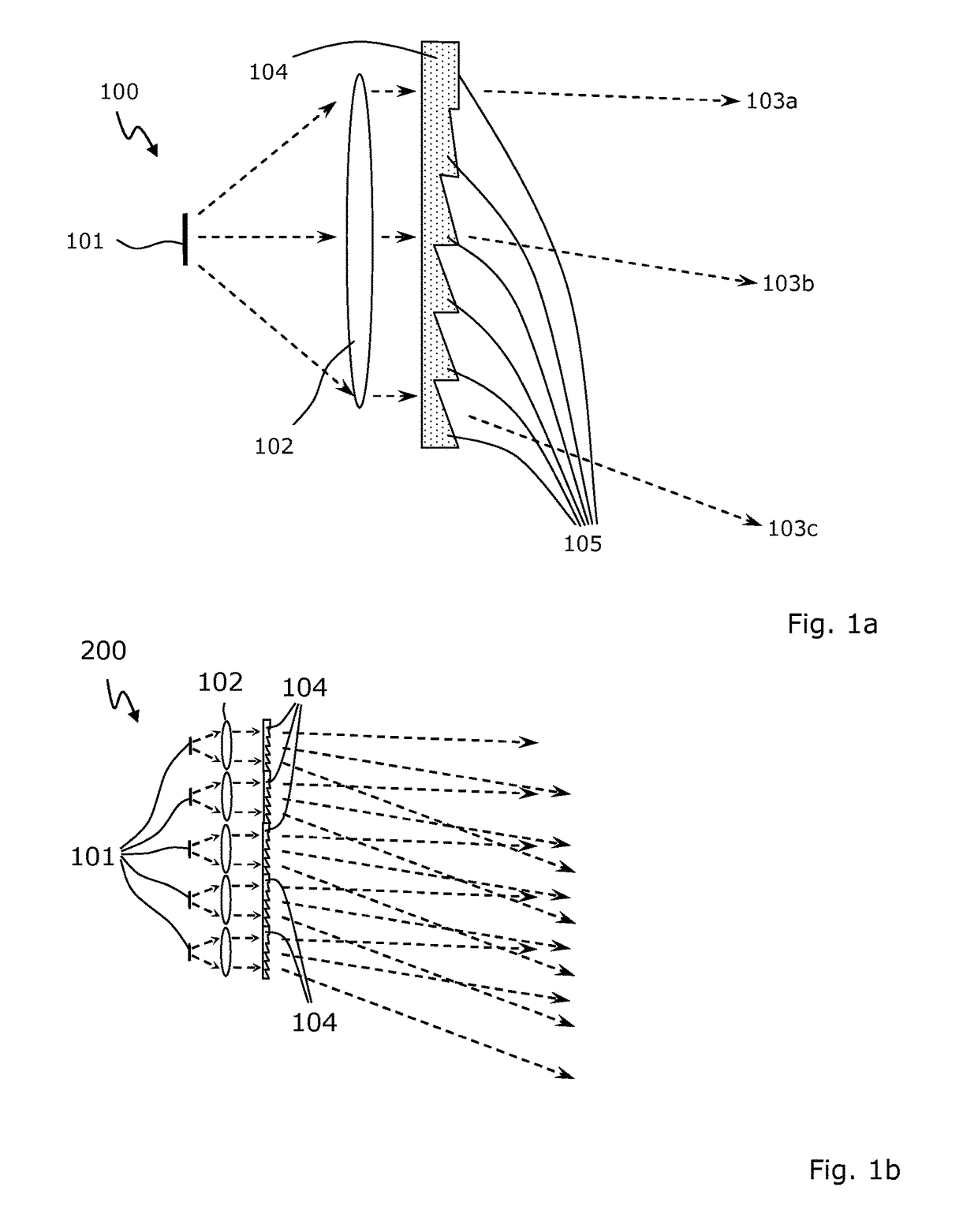
A further disadvantage of the above described configuration is that due to the zone division of the refractive distributor and depending on the angular position of the viewer, only a part of the surface of the distributor seems to be luminous, which leads to an inhomogeneous and sometimes non-circular light distribution on the signal surface.
Moreover, the lifetime and the power efficiency of light bulbs are quite poor and lead to high maintenance costs.
However, by doing so, the electrical design of the signal can change significantly which also has an impact on the optical output flux of the luminaire, both limiting the scalability of this architecture.
In other words LEDs suffer from low brightness requiring the use of tens of LED, thus leading to more complex and costly architectures.
Additionally, because of the small size of the distributors, it is more difficult to shape a sharp angular distribution.
Due to the described limitations, the light distribution of this kind of signal is far less efficient than the one achievable with single light sources.

Method used


Image

  • Universal traffic light luminaire
  • Universal traffic light luminaire
  • Universal traffic light luminaire

Examples


example 1

[0065]A uniform circular light source surface emitting uniformly in a light cone with apex angle 2α (multi-mode fiber output for example):[0066]Constrain on the source flux φ (in [lm]):

ηcφ>∫∫Id(θxφ)dΩ[0067]where φ is the source flux, ηc the source collection efficiency (ratio of source flux emitted by the light sources and output flux of the luminaire, assumed that there are no losses in the collimating optics and in the distributor), Id(θ, φ)(in [lm / sr]) the required distribution diagram intensity, dΩ the differential far field solid angle, and θ, φ correspond to spherical coordinates.[0068]Constrain on the source divergence:[0069]For maximum collection efficiency (ηc=1), the source must illuminate the full signal diameter

[0070]tan⁢⁢α=D2⁢f[0071]where α is the divergence of the light source, D is the signal diameter (which corresponds to the diameter of the collimated beam) and f the focal length of the collimating system.[0072]Constrain on the source size:

h<2f tan δ[0073]wher...

example 2

[0076]A uniform square light source surface with a lambertian emission (HP LED for example):[0077]Constrain on the source flux φ (in [lm]):

ηcφ>∫∫Id(θ,φ)dΩ[0078]where φ is the source flux, ηc the source collection efficiency, Id(θ, φ) (in [lm / sr]) the required distribution diagram intensity, dΩ the differential far field solid angle, and θ, φ correspond to spherical coordinates.[0079]Constrain on the source divergence:[0080]The source been lambertian (i.e. Is=Imax cos(θ)), the collection efficiency is given by:

[0081]ηc=∫02⁢π⁢∫0α⁢Is⁢sin⁢⁢θ⁢ⅆθ⁢ⅆφ∫02⁢π⁢∫0π / 2⁢Is⁢sin⁢⁢θ⁢ⅆθ⁢ⅆφ=1-(cos⁢⁢α)2[0082]with:

[0083]tan⁢⁢α=D2⁢f,[0084]where D is the signal diameter and f the focal length of the collimating system.[0085]Constrain on the source size:

h<2f tan δ[0086]where 2δ is the distribution diagram resolution (i.e. the smallest angular feature in the distribution), and h is the diameter of the source.[0087]Those constrains can also be expressed relatively to the source brightness L (in [lm / sr / m2...


PUM


Abstract

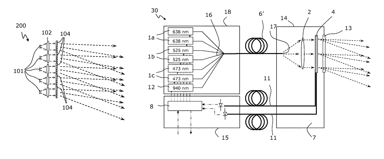
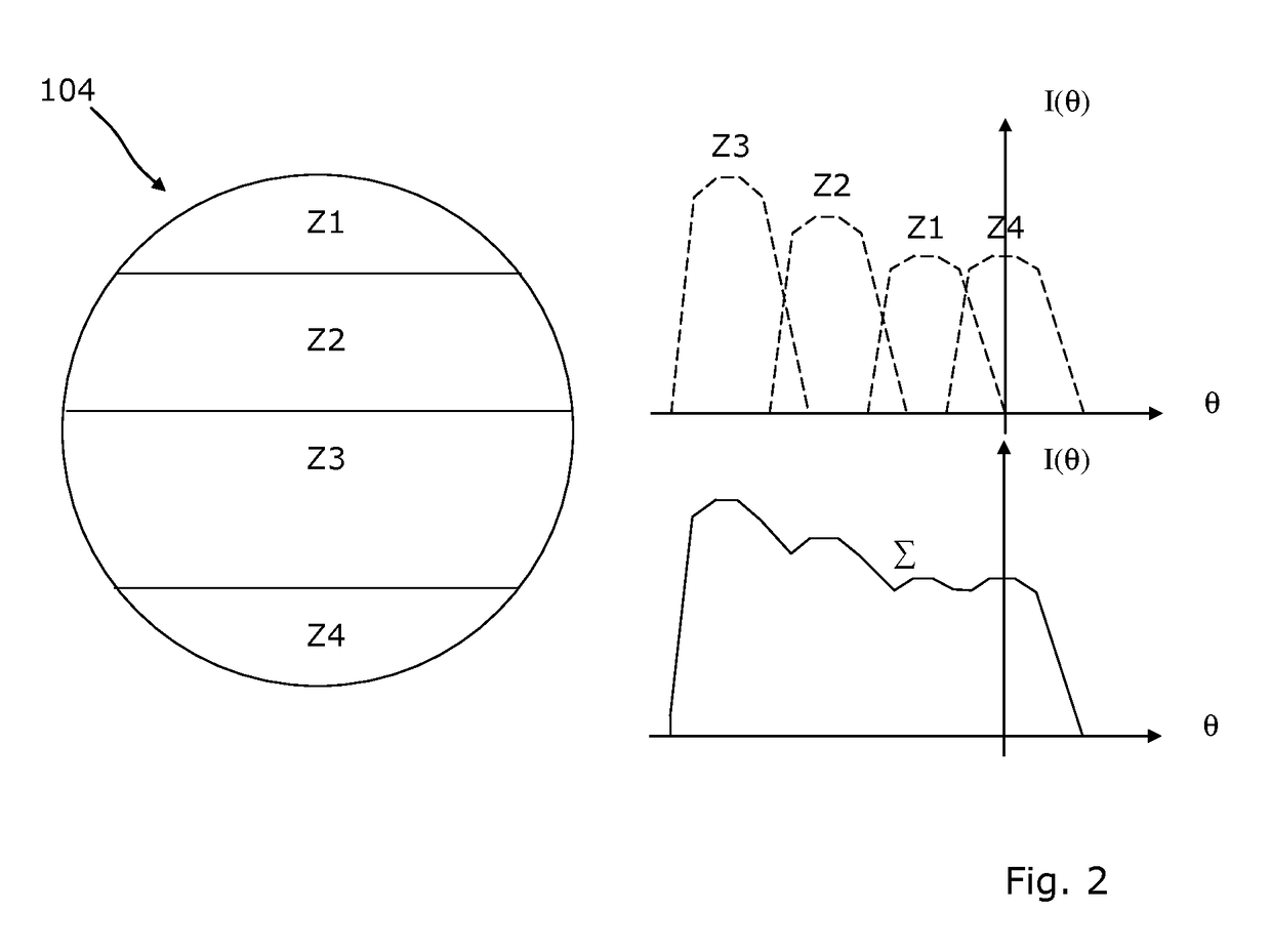
A traffic light luminaire includes at least one light source, a collimating device for collimating light emitted by the at least one light source, and a light distribution device for spreading the collimated light within a specific solid angle with a specific luminous intensity distribution. The light source is a high brightness light source, and the light distribution device is a microstructured distributor having a micro-structured surface, wherein each equal-sized macroscopic section of the microstructured distributor contributes to the luminous intensity distribution in the same way within said whole specified solid angle. Thereby a low maintenance traffic light luminaire is provided which generates a homogeneous light distribution for a variety of trail arrangements (right curve, left curve, straight line) independent of the distance of the viewer.

Description

CROSS-REFERENCE TO RELATED APPLICATIONS[0001]This continuation application claims priority to PCT / EP2013 / 068958 filed on Sep. 12, 2013 which has published as WO 2014 / 041099 A2 and also the European application number 12 184 456.7 filed on Sep. 14, 2012, the contents of which are fully incorporated herein with these references.FIELD OF THE INVENTION[0002]The invention concerns a traffic light luminaire including at least one light source, a collimating device for collimating light emitted by the at least one light source, and a light distribution device for spreading the collimated light within a specific solid angle with a specific luminous intensity distribution.BACKGROUND OF THE INVENTION[0003]In special lighting applications, in particular in traffic signalling, the light is to be emitted according to a pattern that corresponds to positions where the user needs to see a signal. To this end the classical architecture which has been used for tens of years includes a single light so...

Claims


Application Information

Patent Timeline
Patent Type & Authority Patents(United States)
IPC IPC(8): F21V8/00F21V5/04F21V9/04F21Y101/00
CPCG02B6/0006F21V5/04F21V9/04F21Y2101/00F21Y2115/30F21Y2115/10
Inventor LARAT, CHRISTIANWARMUTH, ALFREDJOESTINGMEIER, HORSTCZARNY, ROMAINLOISEAUX, BRIGITTECASTERA, JEAN-PAUL
Owner THALES DEUTLAND GMBH
Learn More