Eureka AIR delivers breakthrough ideas for toughest innovation challenges, trusted by R&D personnel around the world.

Development of zwitterionic coatings that confer ultra anti-biofouling properties to commercial reverse osmosis membranes

a reverse osmosis membrane and anti-biofouling technology, applied in anti-fouling/underwater paints, pretreated surfaces, separation processes, etc., can solve the problems of affecting the separation capability of membranes, membrane fouling is a serious problem, and the device performance of submerged surfaces is reduced

Active Publication Date: 2017-03-21
KING FAHD UNIVERSITY OF PETROLEUM AND MINERALS +1
View PDF13 Cites 1 Cited by
  • Summary
  • Abstract
  • Description
  • Claims
  • Application Information

AI Technical Summary

Problems solved by technology

Fouling diminishes the performance of devices involving these submerged surfaces and is considered the bottle-neck issue for various applications in the biomedical industry, food processing, and water treatment.
Membrane fouling is a serious problem in processes such as reverse osmosis (RO) water desalination, industrial water treatment, juice concentration, and hemodialysis.
On a separation membrane e.g., a RO membrane, a biofilm matrix forms and acts as a secondary membrane, which adversely affects the separation capabilities of the membrane.
The biofilm causes a significant drop in trans-membrane pressure resulting in a decline in permeate water flux with time.
Furthermore, the physical damage of the membrane caused by the biofilm results in increase in the salt passage (i.e., reduced salt rejection).
To combat the adverse effects of biofouling, membranes must be frequently cleaned with harsh chemicals; chemical treatment of the membrane, in turn, results in shorter membrane life.
The cumulative effect of all these factors causes an enormous increase in operating cost of the desalination process.
However, this technique has not been explored fully in the case of separation membranes, such as RO membranes.
These methods have several limitations.
For example, SAMs require specific surface functionality and, therefore, are limited to gold substrates only.
ATRP methods require the use of harsh solvents, which are not compatible with delicate RO membranes.
Furthermore, the use of solvents in solution polymerization and ATRP would not only damage the delicate RO membrane substrate, but may also lead to high surface roughness, which would diminish anti-biofouling properties of the coated surface.

Method used


Image

  • Development of zwitterionic coatings that confer ultra anti-biofouling properties to commercial reverse osmosis membranes
  • Development of zwitterionic coatings that confer ultra anti-biofouling properties to commercial reverse osmosis membranes
  • Development of zwitterionic coatings that confer ultra anti-biofouling properties to commercial reverse osmosis membranes

Examples


example 1

Synthesis of Copolymer Film and Zwitterion Formation

[0171]Materials and Methods

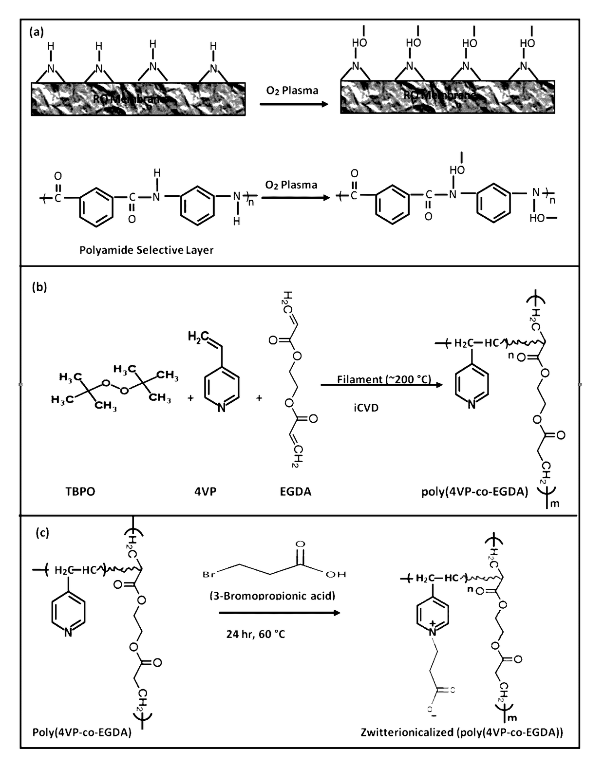
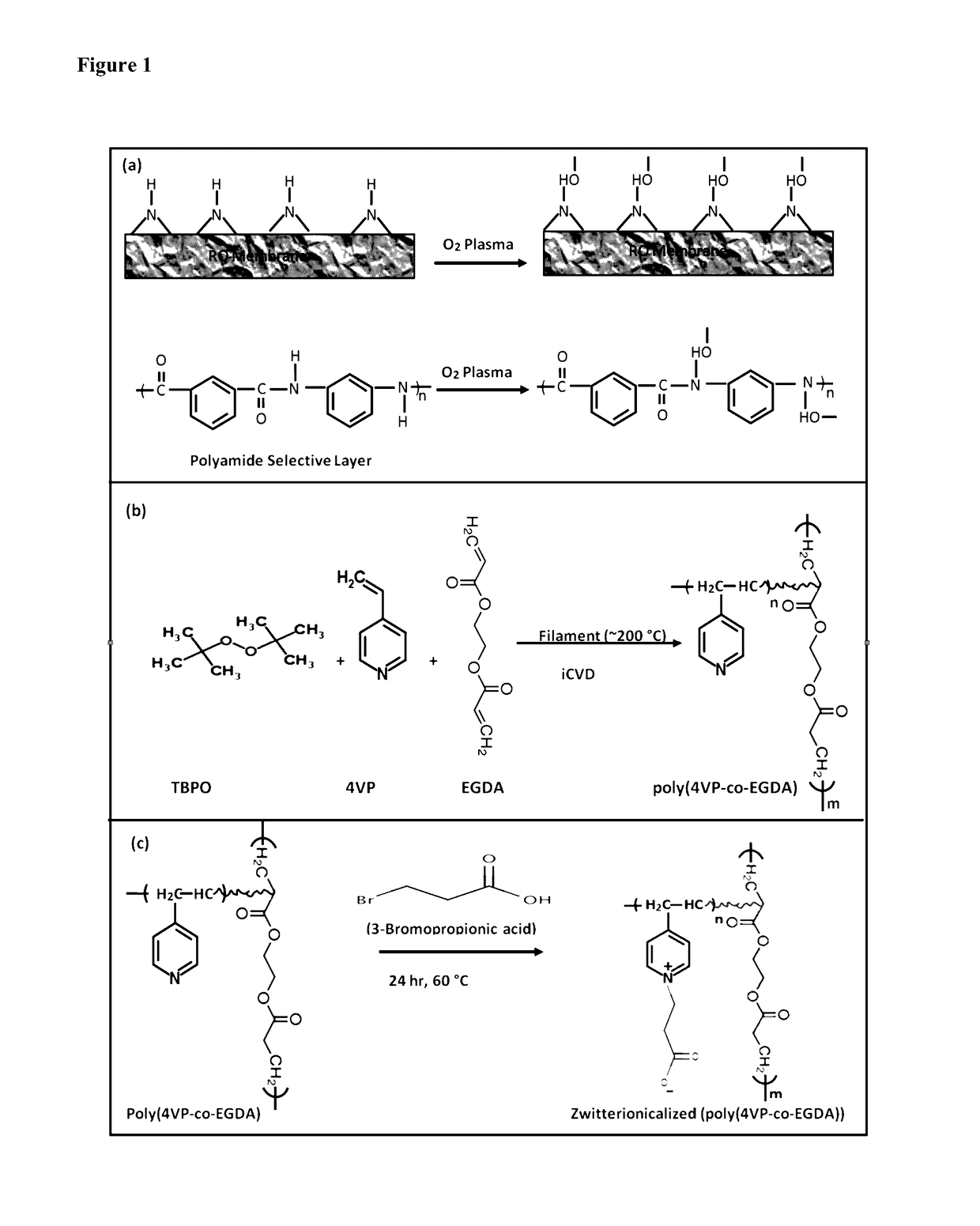
[0172]Different compositions of the same copolymer films p(4-VP-co-EGDA) were deposited in a custom built vacuum reactor (Sharon Vacuum) previously described (Martin, T. P. et al. Biomaterials 2007, 28, 909-915; and Ozaydin-Ince, G. et al. J. Vac. Sci. Technol., A 2009, 27, 1135-1143). The monomers (EGDA (vapor pressure 0.0939 torr at 25° C.) and 4-VP (vapor pressure 1.68 torr at 25° C.)) and initiator (TBPO) were heated in separate glass jars attached to the reactor, and vapors were fed in to the chamber to react on the heated arrays of filament (80% Ni-20% Cr, Goodfellow). Flow rates of both the monomers were systematically changed (while keeping the initiator flow rate fixed) to obtain different compositions of the copolymer.

[0173]All chemicals were used as purchased without further purification. Test grade Silicon (Si) wafers (Wafer World, Palm Beach County, Fla., USA) were coated with copolymer p(4-V...

example 2

Compositional Characterization of Deposited Copolymer Films

[0181]Materials and Methods

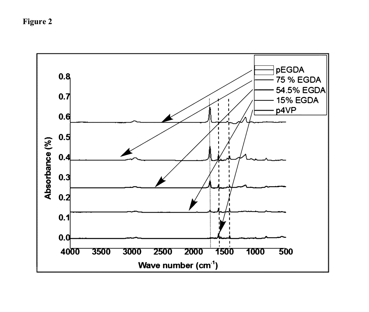
[0182]Nicolet Nexus 870 ESP Spectrometer (Thermo Nicolet, WI, USA) in normal transmission mode was used to obtain Fourier transform infrared (FTIR) spectra. A deuterated triglycine sulfate (DTGS) KBr detector over the range of 400-4000 cm−1 was utilized with a 4-cm−1 resolution. FTIR spectra of deposited Si wafers were measured immediately after deposition or post-treatment, and measured spectra were averaged over at least 100 scans to improve the signal-to-noise ratio. All FTIR spectra were baseline-corrected by subtracting a background spectrum of the Si wafer substrate and smoothed by averaging minimum 10 adjacent points.

[0183]X-ray photoelectron spectroscopy (XPS) survey spectrum and higher resolution spectra of N1s were obtained on a Kratos Axis Ultra Spectrometer (Surface Science Instrument, SSX-100) with a monochromatic Al Kα source. Samples were stored under vacuum overnight prior to analys...

example 3

Surface Hydrophilicity

[0188]Materials and Methods

[0189]Sessile drop contact angle was measured at ambient conditions (25° C. and 1 atm.) by utilizing goniometer equipped with an automatic dispenser (Model 500, Ramé-Hart). A 2-μL droplet of deionized water was placed on the specimen and contact angle was measured immediately after the contact. At least five measurements were performed on each specimen sufficiently apart from each other and the average was reported as the contact angle of the surface under study.

[0190]Results and Discussion

[0191]Contact angle measurement is a well-established method of measuring the hydrophilicity of a surface. Hydrophilicity is characterized by lower values of water contact angle. Lower values of contact angle are also indicative of higher wettability which helps in the formation of surface water layer. It is hypothesized that the non-fouling ability of both polyhydrophilic and polyzwitterionic materials are tightly correlated with a hydration layer ...


PUM

PropertyMeasurementUnit
static contact angleaaaaaaaaaa
timeaaaaaaaaaa
thickaaaaaaaaaa

Abstract

Disclosed are methods of preparing antifouling coatings on reverse osmosis membranes with initiated chemical vapor deposition. The coatings enhance the stability and lifetime of membranes without sacrificing performance characteristics, such as permeability or salt retention.

Description

BACKGROUND OF THE INVENTION[0001]Fouling refers to the undesirable attachment of organic matter, biomolecules, and microbes on submerged surfaces. Fouling diminishes the performance of devices involving these submerged surfaces and is considered the bottle-neck issue for various applications in the biomedical industry, food processing, and water treatment. Membrane fouling is a serious problem in processes such as reverse osmosis (RO) water desalination, industrial water treatment, juice concentration, and hemodialysis. On a separation membrane e.g., a RO membrane, a biofilm matrix forms and acts as a secondary membrane, which adversely affects the separation capabilities of the membrane. The biofilm causes a significant drop in trans-membrane pressure resulting in a decline in permeate water flux with time. To keep the permeate flux at optimum levels, higher operating pressures are required. Furthermore, the physical damage of the membrane caused by the biofilm results in increase ...

Claims


Application Information

Patent Timeline
Patent Type & Authority Patents(United States)
IPC IPC(8): B01D61/00C08F226/10C08F222/10C09D5/16B05D3/14C09D139/08B29C44/04B01D67/00B01D39/00B01D63/00B01D65/08
CPCC09D139/08B01D65/08B01D67/0088B05D3/142C08F222/1006C08F226/10C09D5/1637B01D2321/28C08F2222/1013B01D61/025B01D69/02B01D69/10B01D71/52B01D71/56B01D71/62B01D71/64B01D71/68B01D71/80B01D2325/18C08F222/102
Inventor GLEASON, KAREN K.KHAN, ZAFARULLAHSHAFI, HAFIZ ZAHIDYANG, RONG
Owner KING FAHD UNIVERSITY OF PETROLEUM AND MINERALS
Why Eureka
Eureka Blog
Learn More