
Steerable wheel side of a drive axle

a technology of drive axles and side wheels, which is applied in the direction of steering parts, mechanical equipment, transportation and packaging, etc., can solve the problems of increased difficulty, increased cost, and failure to use drop center steel rims

Active Publication Date: 2017-02-28
KESSLER & CO GMBH CO KG
View PDF15 Cites 4 Cited by
  • Summary
  • Abstract
  • Description
  • Claims
  • Application Information

AI Technical Summary

Benefits of technology

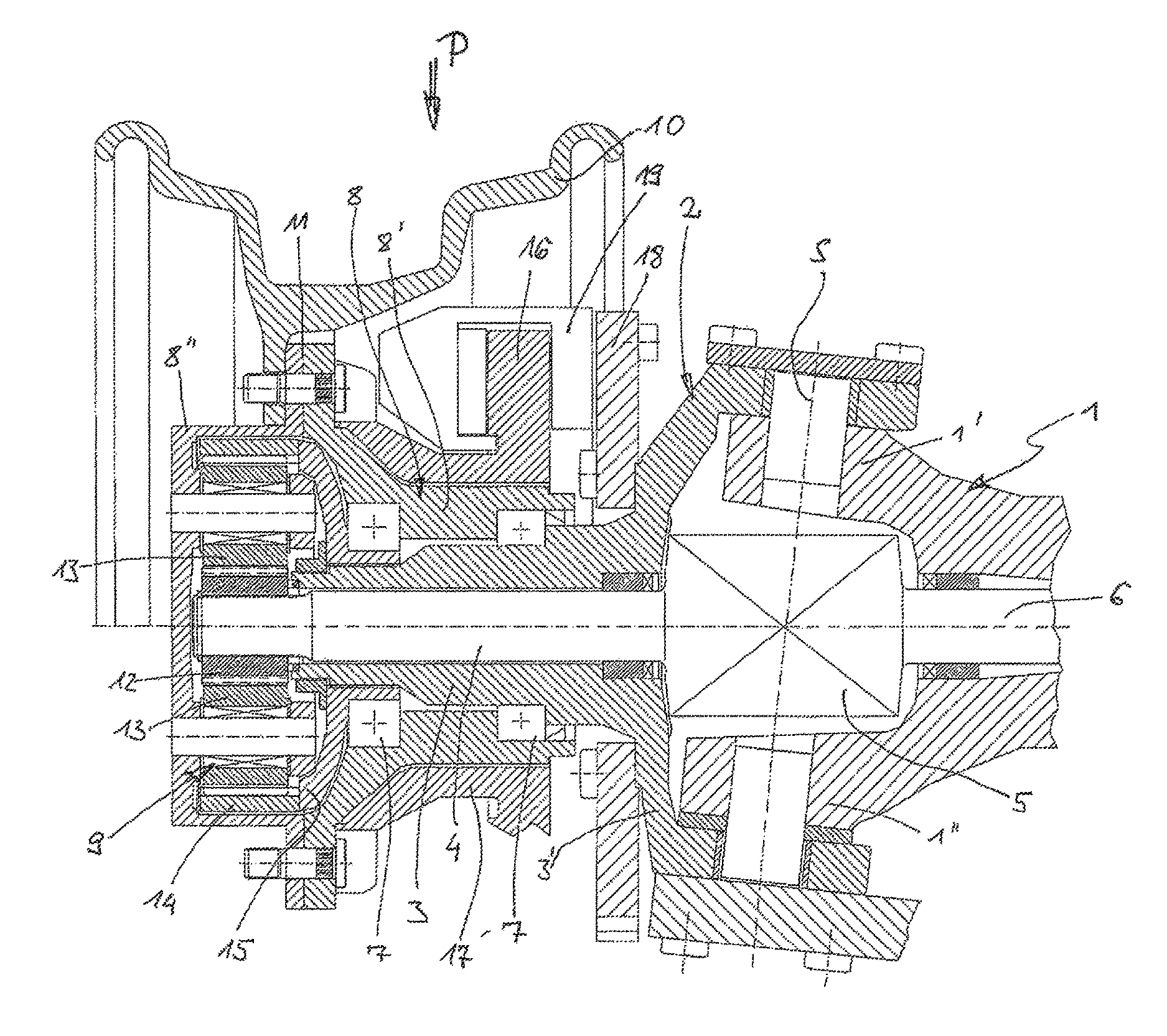
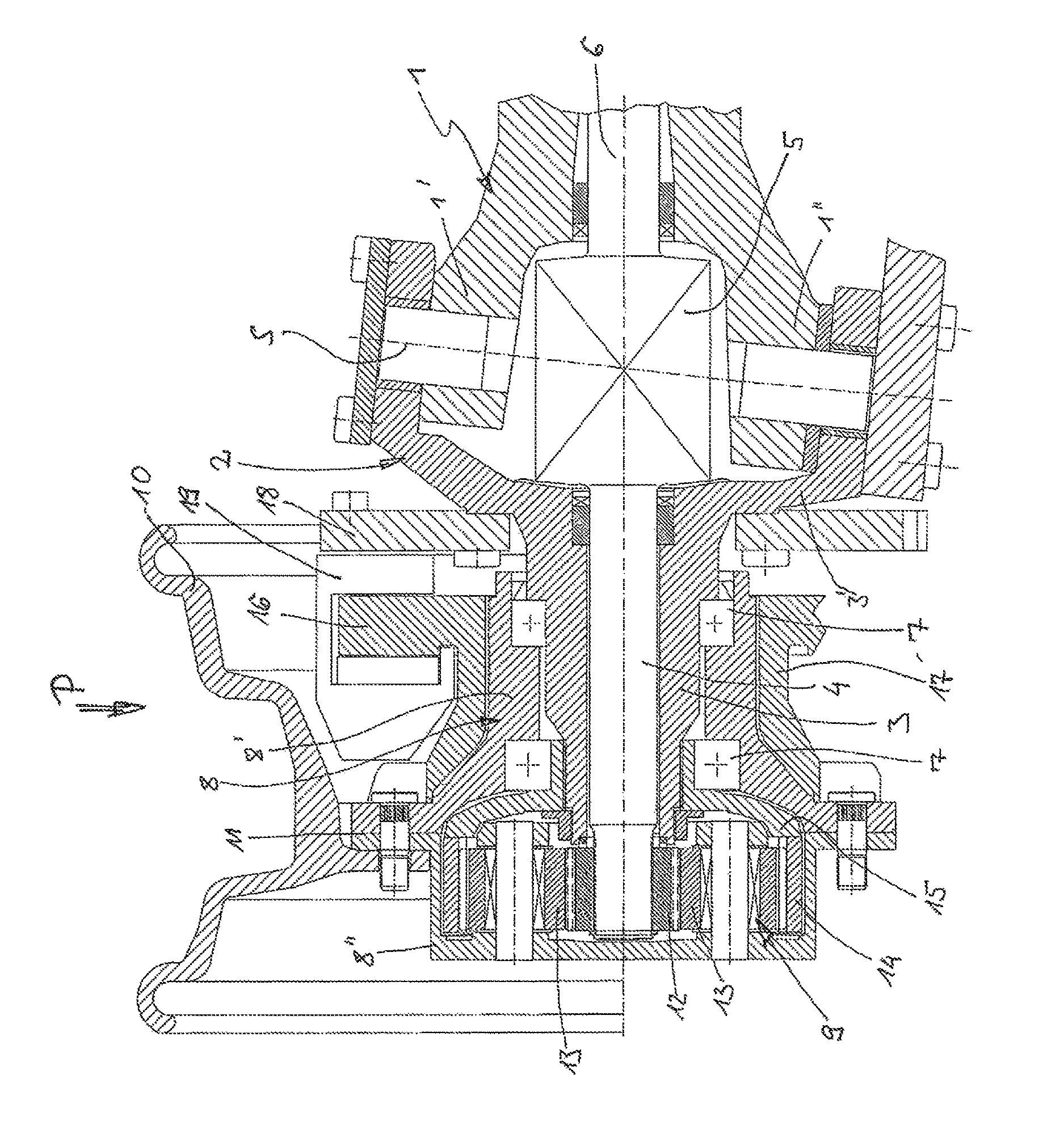
The invention aims to provide a more efficient and space-saving solution for braking on vehicles. It recognizes the advantages of using steel drop center rims over multi-part aluminum rims to save costs, but also addresses potential issues with axle construction. The invention proposes a reduction in the diameter of the wheel hub between the rim and the axle guard, which provides enough space for suitable pneumatic disk brakes. Additionally, the invention optimizes the axle guard spacing to match the size of the joint connection between the shaft part passing through the knuckle and a drive shaft in the middle axle section. This helps prevent interference with the brake system arrangement. The invention also recommends configuring the wheel hub gear as axially narrow to avoid interfering with brake system construction. Overall, the invention provides a feasible solution for braking on vehicles while saving costs and increasing space efficiency.

Problems solved by technology

Having regard to weight-critical cases of application, expensive, dismantlable aluminum rims are customary in this connection.
However, the use of drop center steel rims has previously failed in that the spatial conditions at a drive axle having Ackermann steering does not permit the use of disk brakes (preferably actuated by compressed air).
This is because in contrast to the multi-part dismantlable rims which can have a very flat rim base due to their dismantling capability, a sufficient accommodation space for disk brakes dimensioned in accordance with the conditions of use of the respective vehicles is not available radially within the drop center steel rims, with the additional difficulty that the customary 25 inch tires require a particularly deep drop center for their mounting.

Method used


Image

  • Steerable wheel side of a drive axle
  • Steerable wheel side of a drive axle

Examples


Embodiment Construction

[0021]In accordance with the drawing, the invention relates to a drive axle having Ackermann steering. In this respect, a middle section of the axle, which as a rule comprises the respective axle differential, has an axle guard at its two ends, the axle guard having an upper guard end 1′ and a lower guard end 1″, at which ends a knuckle support 2 having a knuckle 3 connected in one piece to a knuckle cap 3′ is arranged in a steerable manner about a pivot axis S predefined by the guard ends 1′ and 1″. The knuckle 3 is configured as a hollow body and receives a drive shaft part 4 in an axial central bore, with the drive shaft part being connected drive-wise to a drive shaft 6 arranged in the middle axle section via a joint connection 5 arranged in a free space between the knuckle cap 3′ and the guard ends 1′ and 1″. A wheel hub arrangement 8 is rotatably supported at the knuckle 3 by means of roller element bearings, in particular cone bearings 7, and is in a drive connection with the...


PUM


Abstract

The wheel side of a drive axle with wheel member steering having a drop center rim, preferably made of steel, is provided on the wheel hub and is combined with a disc brake, which is axially inwardly offset relative to the wheel plane and which preferably has compressed an actuation. The necessary space for the disc brake arrangement is guaranteed by the sufficiently low diameter of the wheel hub in the region of the brake disc and by a comparatively large axial space for the brake system, which is created by an axially narrow design of the wheel hub transmission and a by a new design of the steering knuckle bearing and of the pertaining axle guard.

Description

CROSS-REFERENCE TO RELATED APPLICATIONS[0001]This application is the U.S. National Phase of PCT / EP2014 / 053277 filed Feb. 20, 2014, which claims priority of German Patent Application 10 2013 206 545.0 filed Apr. 12, 2013.BACKGROUND OF THE INVENTION[0002]Field of the Invention[0003]The invention relates to steerable wheel sides of a drive axle for heavy crane vehicles or the like, having a knuckle support which is arranged in a steerable manner at an axle guard of a middle axle section and which has a knuckle axially passed through by a drive shaft part, at which a wheel hub and / or a hub carrier having a wheel hub gear is rotatably supported, with the wheel hub gear being drive-connected to the drive shaft part at an input side.[0004]Description of the Prior Art[0005]Axles which are configured as drive axles and which have Ackermann steering for heavy freight vehicles and / or special-purpose vehicles regularly have steerable wheel sides of the initially named kind.[0006]Such axles are ...

Claims


Application Information

Patent Timeline
IPC IPC(8): B60K17/30F16D65/12B60B35/16B60B35/12B60K17/04B62D7/18B60B35/00F16D65/02
CPCB60K17/303B60B35/003B60B35/122B60B35/163B60K17/043B62D7/18F16D65/12F16D65/123B60B35/125B60K17/046B60Y2200/15B60Y2200/416F16D2065/134B60K17/306
Inventor BITTLINGMAIER, GUNTER
Owner KESSLER & CO GMBH CO KG
Learn More