Milling tool

a technology of milling tool and tool head, which is applied in the direction of manufacturing tools, gear teeth, manufacturing apparatus, etc., can solve the problems of reducing the production efficiency of hob cutters

Inactive Publication Date: 2017-02-28
SANDVIK INTELLECTUAL PROPERTY AB
View PDF23 Cites 0 Cited by
  • Summary
  • Abstract
  • Description
  • Claims
  • Application Information

AI Technical Summary

Benefits of technology

[0013]The present invention aims at obviating the above-mentioned disadvantages of previously known milling tools and at providing an improved milling tool. Therefore, a primary object of the invention is to facilitate—and shorten the time for—replacement of the milling inserts, as well as provide conditions to, if required, be able to use differently long milling inserts in one and the same tool body. In particular, the tool body should be able to alternately receive short standard inserts as well as longer protuberance inserts. A further object is to simplify and make more effective the manufacture of the tool body and the milling inserts, in particular so far that the seats of the basic body as well as the appurtenant screw holes should be possible to be provided in an effective way at the same time as the milling inserts are rendered a strong design.
[0014]According to the invention, by placing the screw holes of the seat at a distance from the radial support surface that is greater than its distance to the radially outer end of the axial support surface, the same will be located near the periphery of the cam. Simultaneously, only the radially outer hole in the milling insert is utilized for the receipt of the screw that is tightened in the screw hole. In such a way, the screw and the key grip thereof will be easily accessible even if the cam is situated close to another cam, e.g. of a hob cutter. By furthermore locating the screw hole and the holes in the milling insert, respectively, in such a way that double eccentricities are provided, the inherent elasticity of the screw can be utilized to prestress the same, more precisely so that the same resiliently presses the milling insert against the radial support surface as well as the tangential support surface. Therefore, by means of this solution, conditions are provided so as to, if required, replace a certain type of milling insert, e.g. a short standard insert, by another type of milling insert, e.g. a longer protuberance insert. In such a way, one and the same basic body can be equipped with differently long milling inserts.
[0019]In one embodiment, it applies that a first hole and a second hole mouth in the clearance surface of the milling insert, the first hole having a greater mouth in the clearance surface than the second hole. In such a way, the milling insert retains good strength in the material portion against which the screw head is pressed upon the tightening of the screw. In such a way, also the risk of chips and dirt entering the hole that does not have a screw inserted decreases. In such a way, also the risk of incorrect mounting decreases, in case the first hole has a greater mouth in the form of a countersink.
[0022]In one embodiment, the two holes of the milling insert are formed so that their respective centre axes are situated in a symmetry plane situated halfway between the chip surfaces of the milling insert. In such a manner, the possibility of forming a milling insert with four usable cutting edges is improved.
[0024]In one embodiment, each seat comprises only one screw hole. This entails a less costly manufacture of the basic body.
[0025]The invention according to a second aspect may be realised with an insert kit of differently long milling inserts, which individually have an elongate basic shape and comprise two opposite and mutually parallel chip surfaces, two opposite and mutually parallel clearance surfaces, a pair of opposite ends, as well as two holes, which holes extend continuously between the clearance surfaces, each one of the two chip surfaces transforming into connecting clearance surfaces via a pair of alternately usable cutting edges having identical shape. The insert kit is such that the same comprises two sets of differently long, although equally wide milling inserts, each longer milling insert of which has the two holes thereof located at a mutual distance (L3) that is smaller than the mutual distance (L3) between the two holes (21, 22) in a shorter milling insert, a distance (L4) between the respective holes (21, 22) and the distal end thereof being equally large for a longer milling insert as well as for a shorter milling insert. The advantage of this is that differently long milling inserts can be mounted in one and the same insert pocket, which eliminates the need of double tool sets.

Problems solved by technology

Such a tool can only mill out a single slot.
A disadvantage of the long-edge milling cutter as well as the simple slitting cutter is, however, that the machining becomes comparatively time-consuming and thereby expensive, more precisely as a consequence of the milling having to be carried out in steps in a number of reciprocating relative motions.
Irrespective of embodiment, such hob cutters are expensive to manufacture.
The large investment cost of the tool body is, however, compensated more than enough by the efficiency of the milling cutter.
A disadvantage of these milling inserts is, however, just the fact that they have only one usable cutting edge.
Therefore, the total machining cost is severely burdened by the costs of the milling inserts.
When previously known milling tools having four-edged milling inserts are used for the gear milling of, for instance, cogwheels, problems may arise as a consequence of the requirements of dimensional accuracy and surface smoothness of the cog flanks varying.
The fact that previously known standard inserts and protuberance inserts are differently long, in combination with the same including a single central hole to allow indexing, means that they cannot be used in one and the same tool body.
Therefore, workshops that should be able to provide roughed as well as finished cog details have to invest in two separate tool bodies, which individually are extraordinarily expensive, in particular when it comes to hob cutters of a complicated shape.
Another disadvantage of previously known milling tools of the kind in question is based on the fact that the only hole included in the milling insert is centrally placed in the same, i.e., halfway between the two ends of the milling insert as well as the two chip surfaces thereof.
If the hole is oriented perpendicular to the neutral plane of the milling insert—to be tightenable in a threaded screw hole oriented perpendicular to the axial support surface of the receiving seat—the tightening of the fixing screw is made more difficult in those cases (long-edge milling cutters and hob cutters, respectively) when the tool includes a plurality of cams situated close to each other.
The central location of the hole then means that a key grip included in the head of the screw becomes particularly difficult to access.
Considering that the tools include a considerable number of milling inserts, the requisite and fairly frequent insert replacements become time-consuming and cumbersome.
In such a way, also the risk of chips and dirt entering the hole that does not have a screw inserted decreases.
In such a way, also the risk of incorrect mounting decreases, in case the first hole has a greater mouth in the form of a countersink.

Method used


Image

  • Milling tool
  • Milling tool
  • Milling tool

Examples


Embodiment Construction

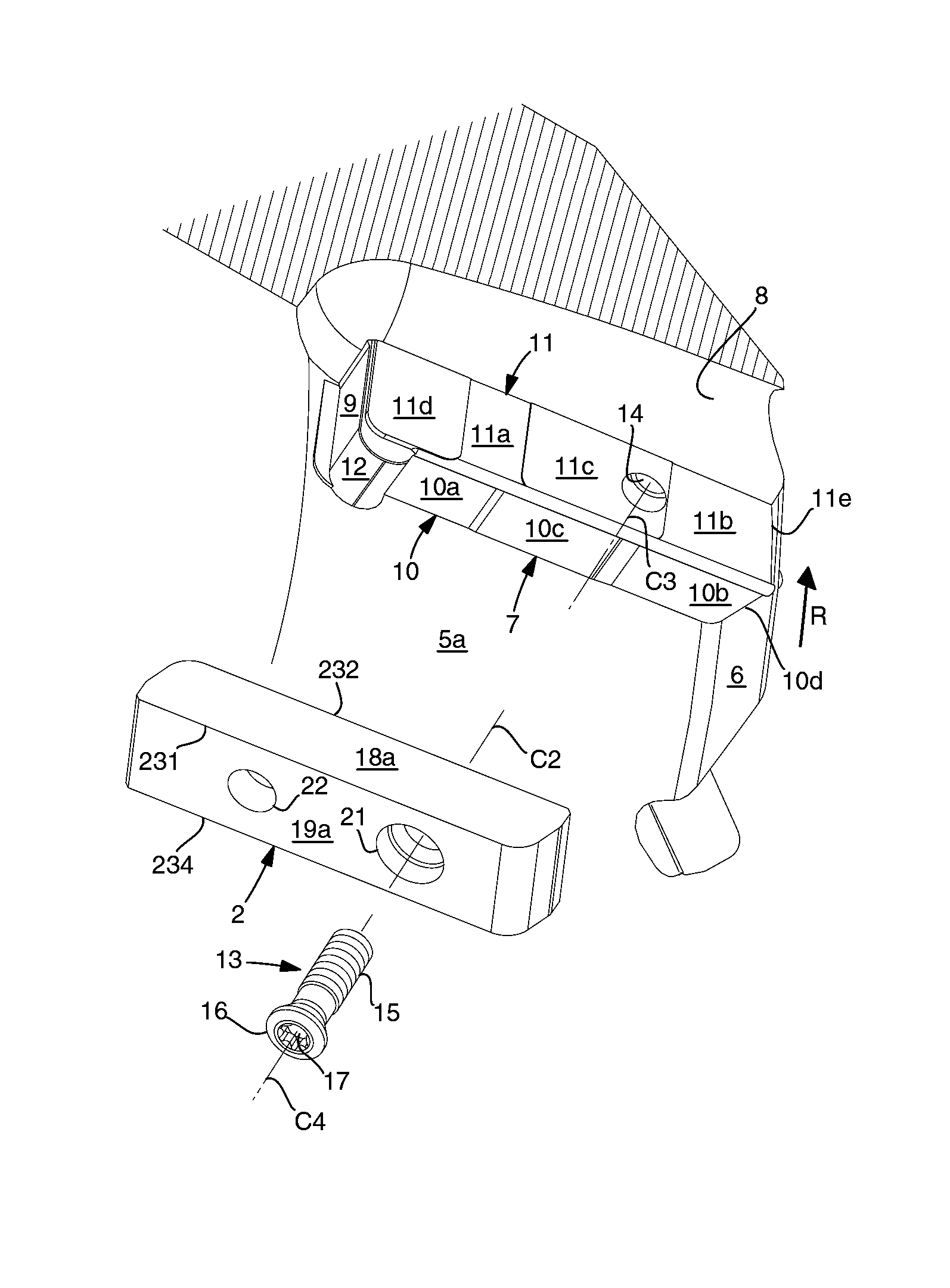
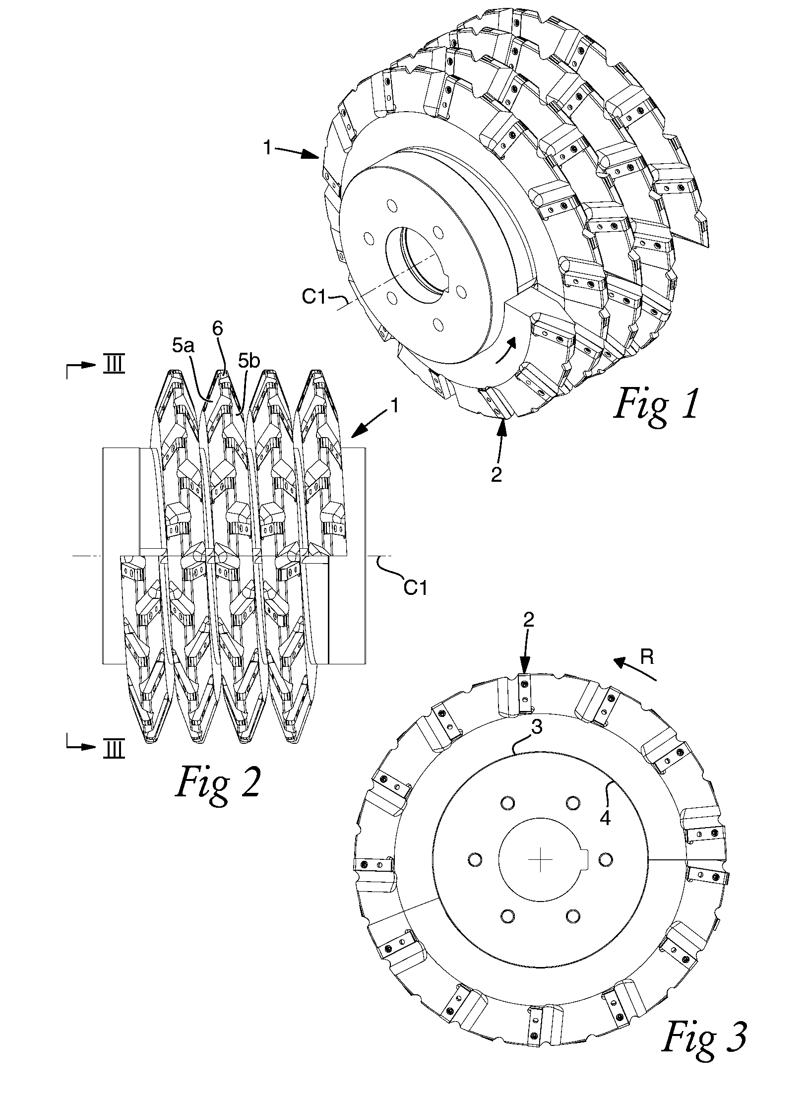
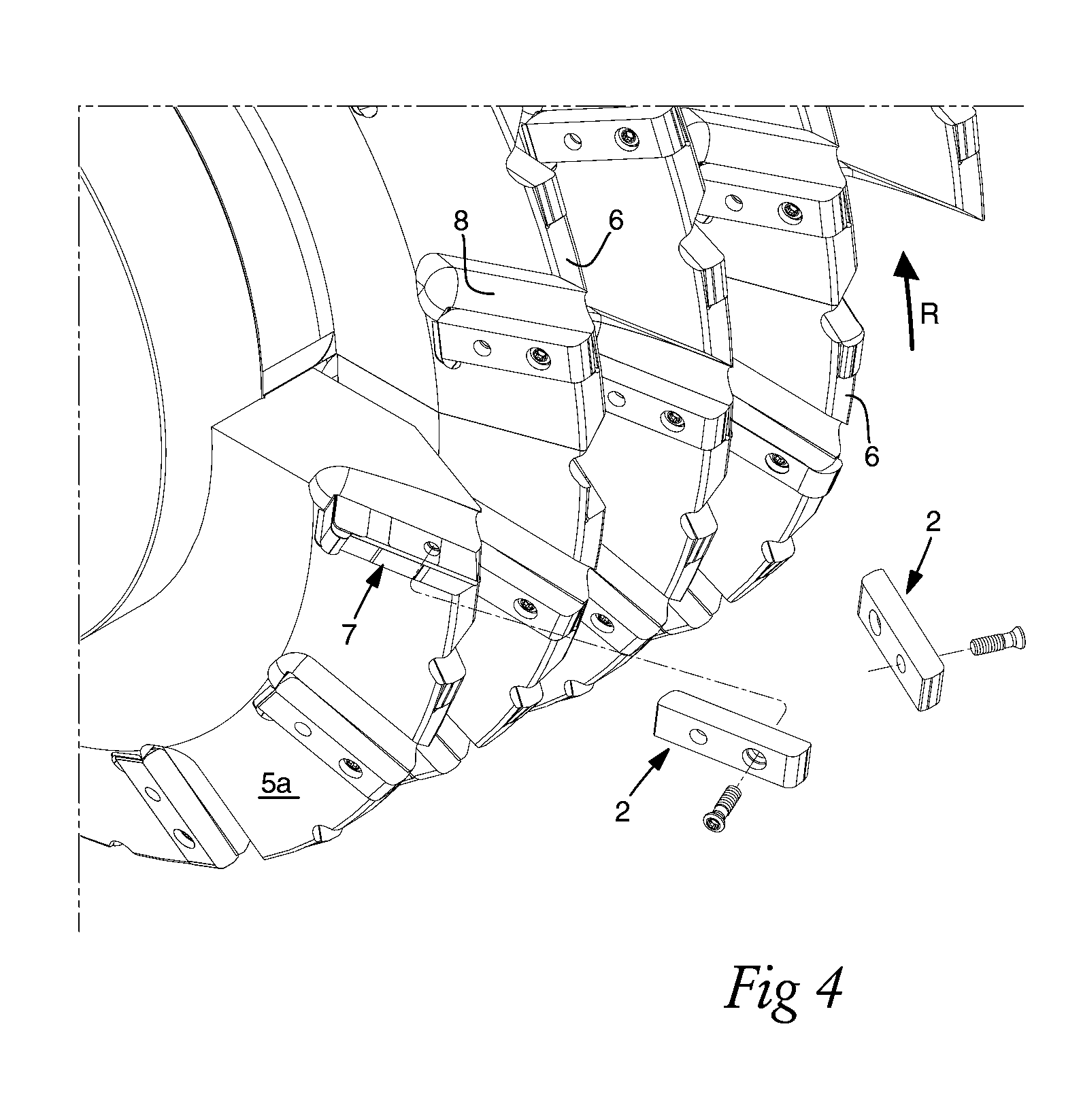
[0048]In FIGS. 1-3, an example is shown of a milling tool according to the invention, more precisely in the form of a hob cutter, which includes a basic body in its entirety designated 1, as well as a plurality of replaceable milling inserts 2. The basic body 1 is rotatable on a centre axis C1 and includes a central core 3 as well as a peripheral cam or ring 4. In the example shown, the cam 4 is composed of a plurality of separate segments, which are mounted outside the core 3 (by those skilled in the art such tools are, therefore, denominated “segment hobs”). The radially outer part of the cam 4 includes two flank surfaces 5a, 5b, which converge toward a common peripheral transition surface 6, involving that the outer part of the cam is cross-sectionally V-shaped. Characteristic of hob cutters is that the cam is running in a helicoidal formation on the centre axis C1, more precisely at a uniform pitch. The number of turns of the screw formation should in practice be within the rang...


PUM


Abstract

The invention relates to a milling tool for gear milling. The tool body is equipped with tangentially mounted milling inserts having four cutting edges and two holes, only one of which is utilized for a fixing screw in two of totally four index positions. By locating a screw hole in the seat of the milling insert at a distance from the radial support surface of the seat that is greater than the distance between an individual hole and a distal end of the milling insert, a clamping force is provided by means of the inherent elasticity of the fixing screw. In such a way, the milling insert is pressed against the radial support surface. By means of a transversal eccentricity, the milling insert is also pressed against a tangential support surface in the seat. By means of this construction, the two holes in differently long milling inserts can be formed with equally large distances from distal ends. Thereby, one and the same tool body can be equipped with differently long milling inserts.

Description

RELATED APPLICATION DATA[0001]This application claims priority under 35 U.S.C. §119 to SE Patent Application Nos. 1251005.3, filed on Sep. 7, 2012 and 1251010.3 filed on Sep. 10, 2012, which both the entirety thereof is incorporated herein by reference.TECHNICAL FIELD OF THE INVENTION[0002]This invention relates to a milling tool of the type that comprises on one hand a basic body, which is rotatable on a centre axis and includes a peripheral cam, which is tangent to an imaginary cylinder and delimited by two flank surfaces converging toward a common transition surface, in each one of which flank surfaces there are countersunk a plurality of tangentially spaced-apart seats, each one of which comprises a tangential support surface, a radial support surface, and an axial support surface in which a screw hole mouths that is radially spaced apart from the radial support surface, and on the other hand a plurality of milling inserts, which individually have an elongate basic shape and com...

Claims


Application Information

Patent Timeline
Patent Type & Authority Patents(United States)
IPC IPC(8): B23C5/22B23C5/20B23F21/16B23F21/14
CPCB23F21/166B23F21/146B23C5/2204B23C5/2208B23C2200/0494B23C2200/361B23C2210/244Y10T407/1725Y10T407/23B23C2200/362B23C2210/168B23C5/2213B23C5/20B23C5/22B23C5/08B23C5/06
Inventor SJOO, STURE
Owner SANDVIK INTELLECTUAL PROPERTY AB
Why Eureka
Try Eureka