
Dual QR decomposition decoder for spatially multiplexed MIMO signals

a decomposition decoder and spatial multiplexing technology, applied in diversity/multi-antenna systems, wireless communication, wireless commuication services, etc., can solve the problems of high complexity of decoding spatial multiplexed signals using optimal maximum likelihood (ml) algorithm, sequential m-algorithm process, and often limited processing capability of receivers, so as to increase the data rate of communication system, increase the performance and data rate of system, and increase the effect of optimal maximum likelihood

Active Publication Date: 2017-02-21
MBIT WIRELESS
View PDF6 Cites 0 Cited by
  • Summary
  • Abstract
  • Description
  • Claims
  • Application Information

AI Technical Summary

Benefits of technology

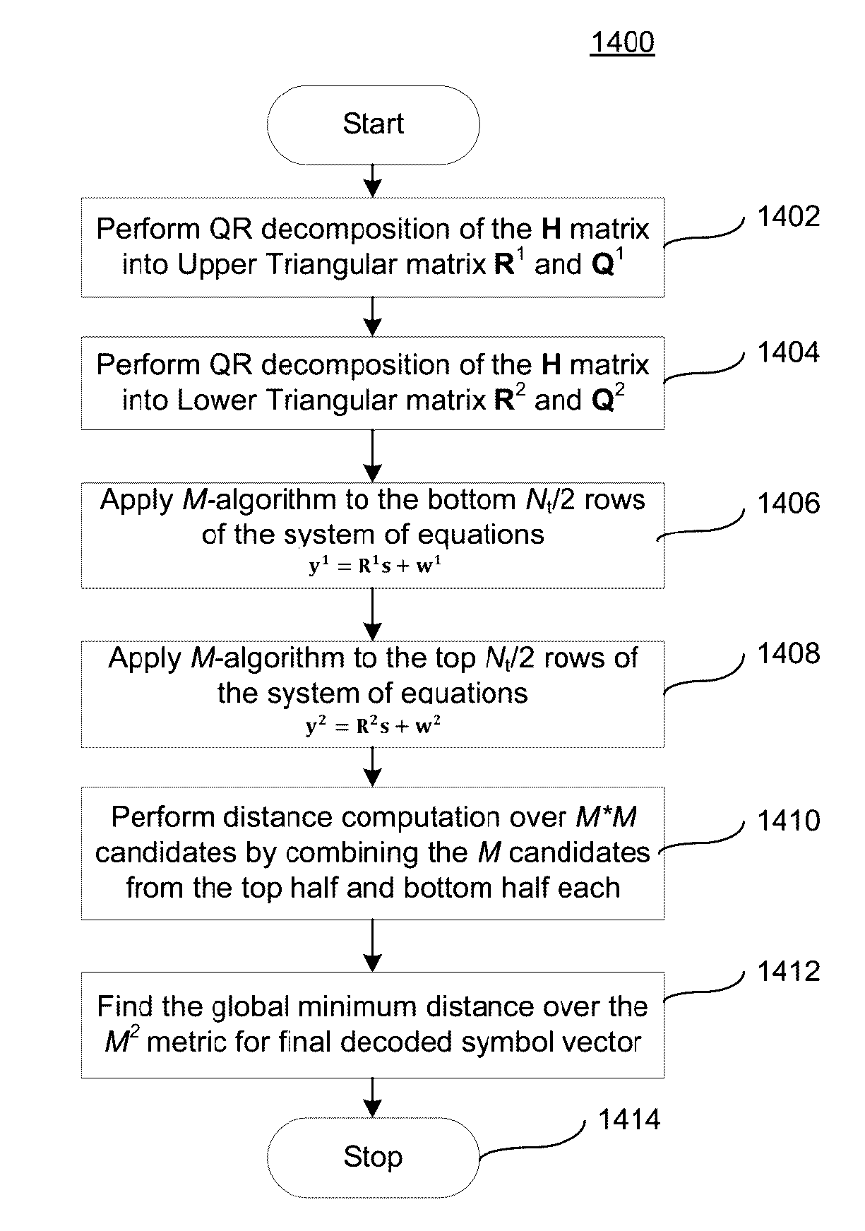
The patent text describes a new approach for decoding spatially multiplexed signals in MIMO wireless communication systems. The approach involves two different QR decompositions of the estimated channel matrix, and processing them in parallel using an M-algorithm process. This approach offers faster processing of the signals, reduces the complexity of the decoders, and offers reduced distance metric computations and search operations. It also results in significant reduction in power consumption, latency, and increases in throughput, leading to more efficient resource use in users' portable wireless communication devices.

Problems solved by technology

The complexity of decoding spatially multiplexed signals using the optimal Maximum Likelihood (ML) algorithm is generally very high and therefore the throughput is often limited by the processing capability of the receiver.
One of the disadvantages of the conventional QRD-M method is that the M-algorithm process is sequential when processing signals from multiple antennas.
Although the sub-optimal decoders are less complex and require less processing when compared to the optimal decoders, the complexity of the sub-optimal decoders still remain high.

Method used


Image

  • Dual QR decomposition decoder for spatially multiplexed MIMO signals
  • Dual QR decomposition decoder for spatially multiplexed MIMO signals
  • Dual QR decomposition decoder for spatially multiplexed MIMO signals

Examples


Embodiment Construction

[0058]The present invention describes a method and apparatus of a QRD-M SM decoder that has reduced complexity and reduced latency when compared to that of the conventional QRD-M SM decoder. To describe the invention, the conventional QRD-M SM decoder is briefly described next.

[0059]The conventional QRD-M SM decoder consists of two main processing blocks as shown in FIG. 10. The first main processing block is the QR decomposition and matrix multiplication and the second main processing block is the M-algorithm.

[0060]The QR decomposition block decomposes the channel matrix H into a right triangular matrix R and a unitary matrix Q using the QR matrix decomposition method. Specifically,

H=QR  (10)

[0061]Since R is a right triangular matrix, all its elements below the main diagonal are zero. A property of a unitary matrix is that its inverse can be obtained by its Hermitian transpose. Specifically,

Q−1=QH  (11)

Therefore,

QHQ=I  (12)

where I is an identity matrix. The Hermitian transpose of a...


PUM


Abstract

Wireless communication systems employ Multiple Input Multiple Output (MIMO) transmission and reception schemes to increase performance and the data rate of the system. A new approach for an SM-MIMO decoder that operates on the received symbols in parallel is presented. The new approach performs two different QR decompositions of the estimated channel matrix and produces two triangular matrices; one is right triangular and the other is left triangular. The modified systems of equations are processed in parallel. After each M-algorithm process has processed half of the total number of stages, total search space for the globally optimal transmitted symbol vector is reduced significantly. Finally, cumulative distance metrics are computed for the symbol sequences in the reduced search space and a global minimum is determined for the estimated transmitted symbol vector. This approach offers faster processing of the SM-MIMO signals and reduced distance metric computations and search operations.

Description

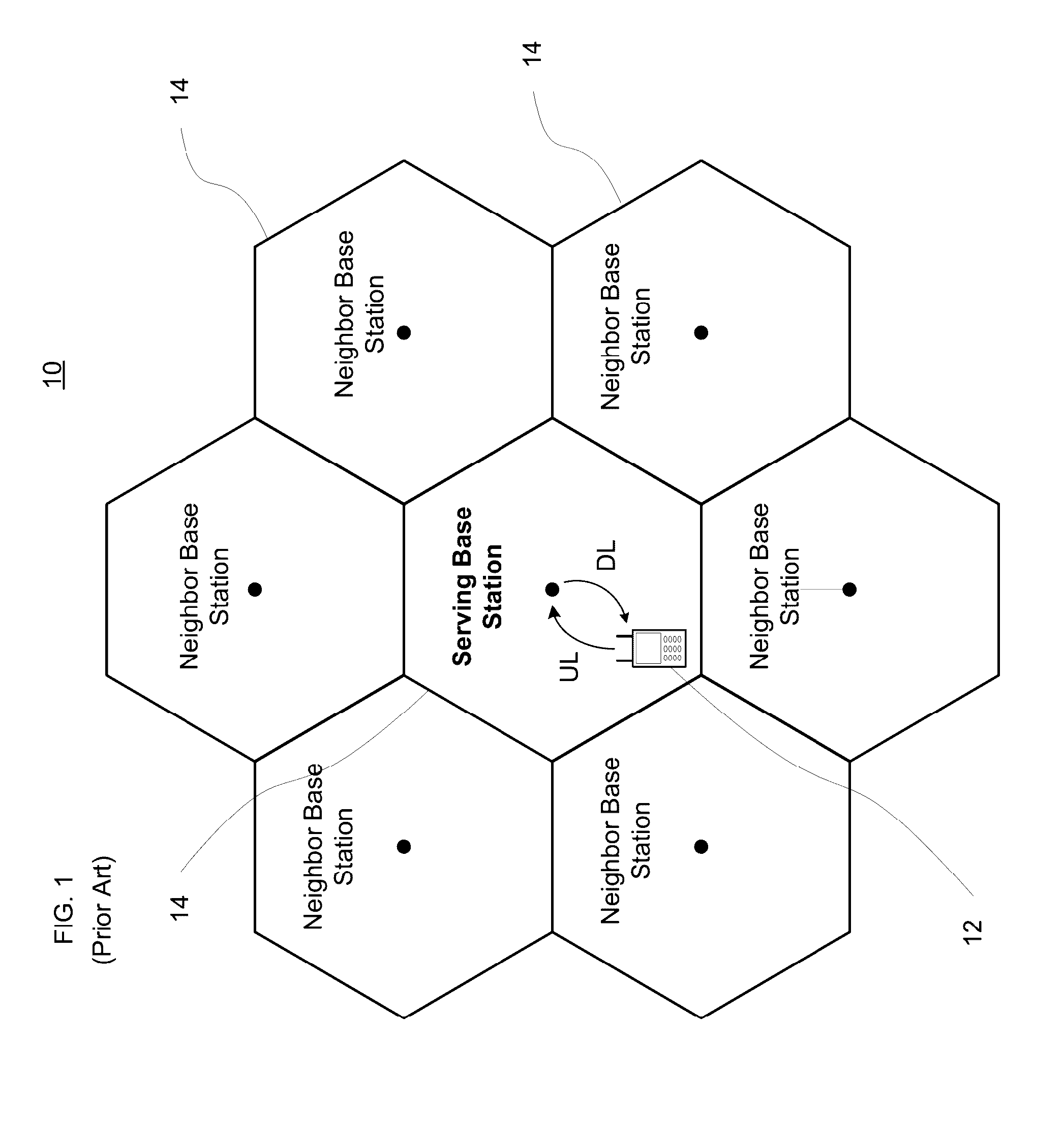
CROSS-REFERENCE TO RELATED APPLICATION[0001]This application is related to U.S. patent application Ser. No. 14 / 537,167, filed concurrently herewith and entitled “Low Latency Spatial Multiplexing MIMO decoder” (the “Low Latency” application) and issued as U.S. Pat. No. 9,118,373, the entire disclosure of which is hereby expressly incorporated by reference herein.BACKGROUND OF THE INVENTION[0002]Field of the Invention[0003]The present invention relates generally to wireless communication systems and, more particularly, to methods and receiver architectures for decoding spatially multiplexed signals used in Multiple Input Multiple Output (MIMO) wireless communication systems.[0004]Description of Related Art[0005]Typically, as shown in FIG. 1, a wireless communication system comprises elements such as client terminals or mobile stations and base stations. Other network devices may also be employed, such as a mobile switching center (not shown). As illustrated, the communication path fro...

Claims


Application Information

Patent Timeline
Patent Type & Authority Patents(United States)
IPC IPC(8): H04W4/00H04B7/06H04B7/04
CPCH04B7/0697H04B7/0413H04L25/03216H04L25/03891
Inventor PATEL, BHASKARGOVINDSWAMY, ARUMUGAM
Owner MBIT WIRELESS
Learn More