
Method for electro-chemical activation of water

a technology of electrochemical activation and water, which is applied in the direction of water/sewage treatment using germicide/oligodynamic process, chemical apparatus and processes, water/sludge/sewage treatment, etc. it can solve the problem that little or substantially none of the catholyte product can be independently harvested for other uses, and the toxicity level of the product is increased. problem, to achieve the effect of reducing the amount of salt used in the dilute brine feed solution, reducing the residual chloride level level

Active Publication Date: 2017-01-03
RADICAL WATERS INT LTD
View PDF39 Cites 2 Cited by
  • Summary
  • Abstract
  • Description
  • Claims
  • Application Information

AI Technical Summary

Benefits of technology

[0018]The present invention provides an electro-chemical reaction apparatus, method and system which satisfy the needs and alleviate the problems discussed above. The inventive apparatus, method, and system operate to: (1) significantly increase the brine conversion ratio in the electro-chemical activation process; (2) significantly reduce the residual chloride levels in the anolyte and catholyte products; (3) allow the amount of salt used in the dilute brine feed solution to be significantly reduced; (4) provide increased catholyte production; (5) reduce the risk of corrosion; (6) increase the life of the system components; and (7) provide increased anolyte production capacity. The present invention also allows the use of smaller brine tanks and reduces or eliminates the need to heat the dilute brine feedstock.

Problems solved by technology

So, for example, at a pH of 3 or below, HOCl tends to convert to Cl2, which increases the toxicity level of the product.
Unfortunately, however, one shortcoming of this procedure for producing a highly effective yet neutral to slightly acidic anolyte which is safe for human consumption is that a significant amount, or sometimes substantially all, of the catholyte is consumed by recirculation through the anodal flow chamber.
Thus, oftentimes, very little or substantially none of the catholyte product can be independently harvested for other uses.
The presence of a higher concentration of unreacted chloride ions in the anolyte product is viewed as presenting an increased risk of corrosion which could shorten the life of the reactor components and coatings.
Moreover, chlorides are already present in most water sources and the addition of any further chloride load can create concerns, for example, for beverage producers and other users of stainless steel processing equipment.
In many cases, the original equipment manufacturer will not guarantee equipment which is exposed to chloride levels of greater than 55 ppm, and in some cases even less.
Unfortunately, to reduce the residual chloride content and increase the FAC levels of these anolyte products using a traditional prior art reactor system configuration, it would be necessary to use a high brine concentration, a very low flow rate, and an increased amount of electrical current.
This would result in premature failure of the reactor system due to coating failure, and would also significantly reduce the amount of anolyte product produced.

Method used


Image

  • Method for electro-chemical activation of water
  • Method for electro-chemical activation of water
  • Method for electro-chemical activation of water

Examples


example 1

[0066]Tests were conducted which involved passing a dilute aqueous brine solution through a modified cylindrical “pre-activation” reactor prior to activating the solution in an unmodified cylindrical reactor cell. The modified pre-activiation reactor comprised an inner anode and outer cathode having the same specifications as used for a regular cylindrical reactor cell, except that the ceramic membrane was removed from between the anode and cathode in the modified cell.

[0067]In the tests, two such modified “pre-activation” reactors were used and two unmodified “activation” reactors of the same type were used, each one of the modified reactors being installed in series prior to one of the unmodified reactors.

[0068]In preliminary tests, the intermediate solution exiting the modified, pre-activation reactors had a relatively high pH of above 8.0 indicating that a mixed oxidant solution was created with hypochlorite being the main component. The intermediate solution had a FAC concentra...

example 2

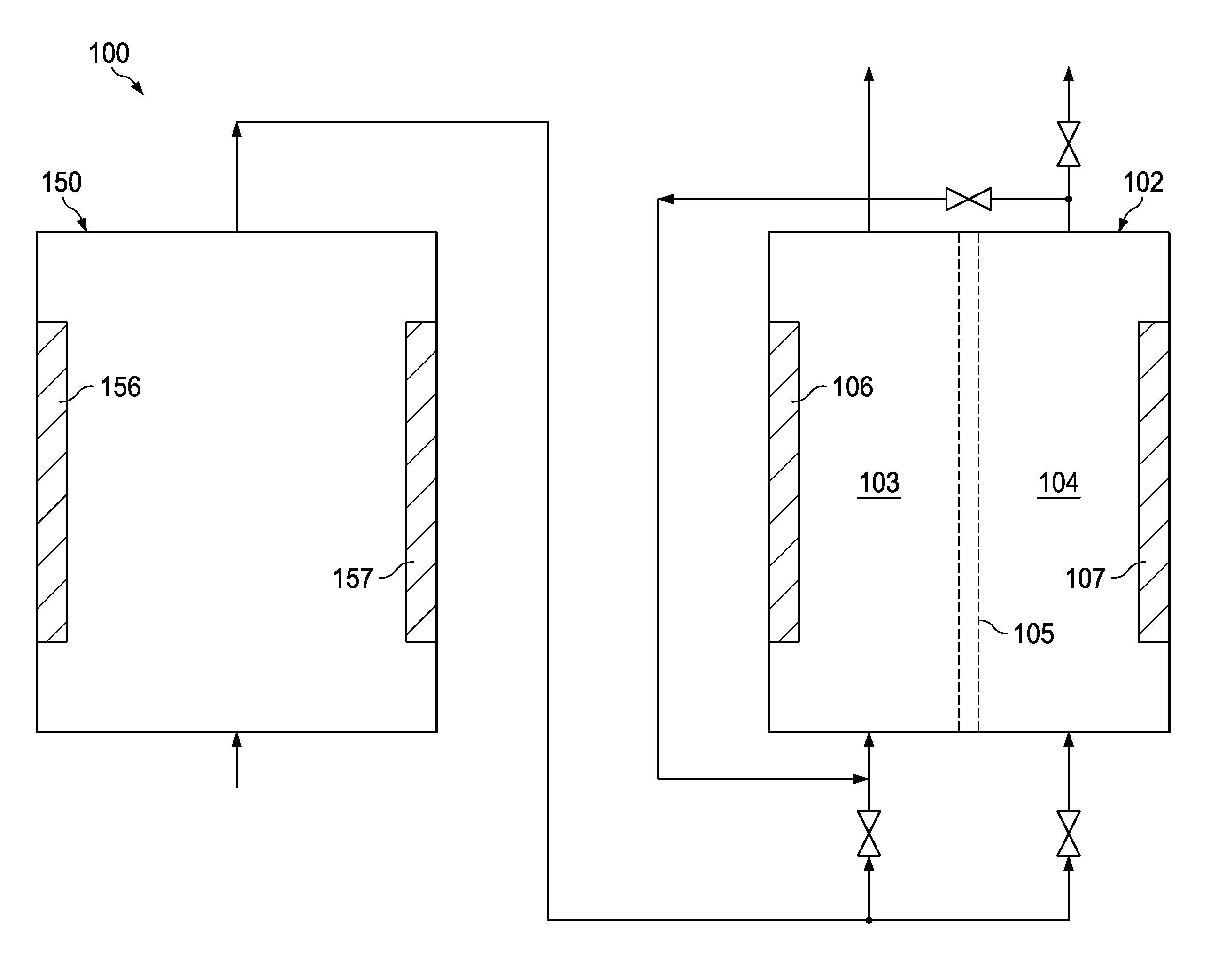
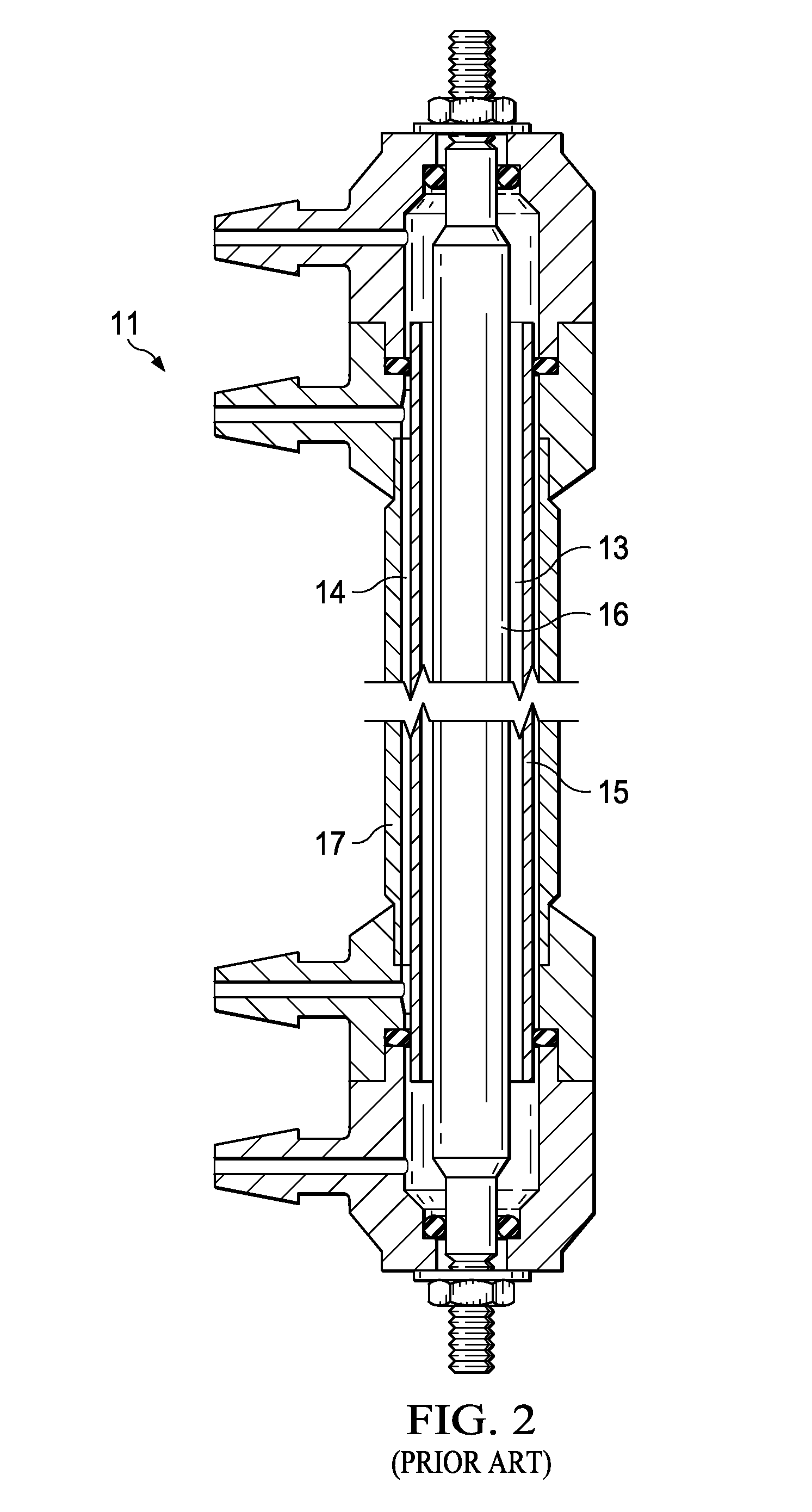
[0077]An inventive, industrial scale activation system was operated using a dilute aqueous feed solution consisting of 0.7 grams of NaCl per liter of water. The source water used for forming the dilute aqueous feed solution was deionized water which had a chloride content of 10-12 ppm. The inventive activation system comprised a preliminary reactor 150 as illustrated in FIG. 4 followed by a block of 12 cylindrical activation reactors of the type illustrated in FIG. 2 operating in parallel. As shown in FIG. 4, the preliminary reactor 150 comprised a block housing 155 having twelve anode plates 156 and twelve cathode plates 157 installed therein in an alternating, parallel, side-by-side relationship with no membrane elements being present in the preliminary reactor 150 between any of the adjacent pairs of anode plates 156 and cathode plates 157.

[0078]The undiluted anolyte product produced by the inventive system had a pH of 6.8, a residual chloride content of 350 ppm by weight, a free...


PUM

PropertyMeasurementUnit
oxidation-reduction potentialaaaaaaaaaa
pHaaaaaaaaaa
oxidation-reduction potentialaaaaaaaaaa

Abstract

An apparatus, system, and method for producing electro-chemically activated water wherein (1) a dilute aqueous salt solution is first delivered through a preliminary reactor which has an anode element and a cathode element but does not have a membrane element positioned between the anode and the cathode and (2) the product from the preliminary reactor is then delivered through an activation reactor having a membrane element positioned between the anode and cathode elements thereof.

Description

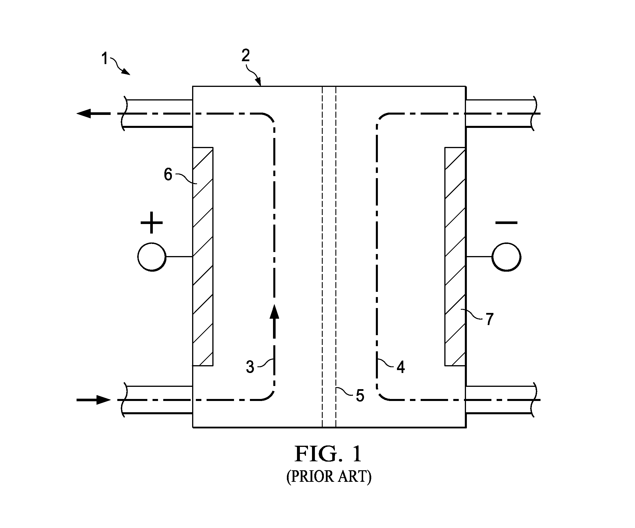
RELATED CASE[0001]This application claims the benefit of U.S. Provisional Patent Application Ser. No. 61 / 777,566 filed on Mar. 12, 2013 and incorporates said provisional application by reference into this document as if fully set out at this point.FIELD OF THE INVENTION[0002]The present invention relates to methods, apparatuses, and systems for producing electro-chemically activated aqueous solutions.BACKGROUND OF THE INVENTION[0003]Electro-chemically activated (ECA) water is produced from dilute dissociative salt solutions by passing an electrical current through the solution to produce catholyte and / or anolyte products. The catholyte, which is the solution exiting the cathodal chamber of the activation reactor cell, is an anti-oxidant which typically has a pH in the range of from about 8 to about 13 and an oxidation-reduction potential (ORP) in the range of from about −200 mV to about −1100 mV. The anolyte, which is the solution exiting the anodal chamber, is an oxidant which typi...

Claims


Application Information

Patent Timeline
Patent Type & Authority Patents(United States)
IPC IPC(8): C02F1/46C02F1/467C02F1/461
CPCC02F1/4674C02F1/4618C02F2001/46142C02F2001/46171
Inventor BUITENDAG, MATHYS JACOBUSNEL, PHILIPJENSEN, DANIEL FRANCOISDU PLESSIS, HENDRIK FREDERIK
Owner RADICAL WATERS INT LTD
Learn More