
Drive unit for switching element

a technology of driving unit and switching element, which is applied in the direction of electronic switching, power conversion system, pulse technique, etc., can solve the problems of excessive surge current, deterioration of the operational reliability of the switching element, and the possibility of generating a large surge voltage, so as to prevent the deterioration of the reliability of the target switching element and suppress the surge current. the effect of magnitud

Active Publication Date: 2016-11-29
DENSO CORP
View PDF10 Cites 5 Cited by
  • Summary
  • Abstract
  • Description
  • Claims
  • Application Information

AI Technical Summary

Benefits of technology

[0008]It is therefore desired to provide a drive unit for driving a switching element, as a target object to be driven or controlled, with a high operational reliability.
[0012]In order to avoid the above drawback, the drive unit according to an exemplary embodiment of the present invention has the processing section. The processing section suppresses a magnitude of the surge current generated when the target switching element is forcedly turned off even if the overcurrent flows in the target switching element under the complete turned-on state of the target switching element. This makes it possible to prevent the deterioration of the reliability of the target switching element.

Problems solved by technology

However, when such an overcurrent protection function is applied to a drive unit in an electric power conversion circuit such as a three phase inverter, there is a possibility of causing the following drawback.
For example, under a condition in which one of the switching element in a high voltage side and the switching element in a low voltage side in each of the series connection units enters a completely turned-on state (or a full turned-on state), and an upper-lower arm short circuit occurs, in which the other switching element, which is not turned on, suffers a short circuit defect, when an overcurrent protection function forcedly cuts off the collector current flowing between the input terminal and the output terminal of the semiconductor switching element, this has a possibility of generating a large surge voltage.
Such a large surge voltage often deteriorates the operational reliability of the switching element in a high voltage side and the switching element in a low voltage side.
Accordingly, in a case in which the target switching element is in the completely turned-on state and an overcurrent flows in the target switching element, the surge current is excessively increased when the target switching element is forcedly turned off.
This deteriorates the operational reliability of the target switching element.

Method used


Image

  • Drive unit for switching element
  • Drive unit for switching element
  • Drive unit for switching element

Examples


first exemplary embodiment

[0026]A description will be given of the drive unit according to a first exemplary embodiment with reference to FIG. 1 to FIG. 5. For example, the drive unit DU according to the first exemplary embodiment is used in an inverter IV which drive and control the operation of a motor generator 10 as an electric rotary machine. The motor generator 10 is a main machine of a motor vehicle (omitted from the drawings). The motor vehicle is also equipped with an internal combustion engine (omitted from the drawings).

[0027]FIG. 1 is a view showing a structure of a motor control system comprised of the inverter IV, a control device 14 and an interface section 18. The inverter IV is comprised of series connection units. Each of the series connection units is comprised of a semiconductor switching element S*p (*=u, v, w) in a high voltage side and a semiconductor switching element S*n (*=u, v, w) in a low voltage side. As shown in FIG. 1, the semiconductor switching element S*p (*=u, v, w) in a hi...

second exemplary embodiment

[0095]A description will be given of the software cutoff process performed by the drive control section 44 in the drive IC 20 in the drive unit DU according to a second exemplary embodiment with reference to FIG. 6 and FIG. 7.

[0096]The second exemplary embodiment discloses the software cutoff process performed by the drive control section 44 which is different from the software cutoff process according to the first exemplary embodiment. The following explanation will show a difference between the second exemplary embodiment and the first exemplary embodiment. The explanation for the same components and processes between the first and second exemplary embodiments is omitted here for brevity.

[0097]FIG. 6 is a view showing a structure of the drive unit DU according to the second exemplary embodiment. The same components between the drive unit DU shown in FIG. 1 and the drive unit DU shown in FIG. 6 will be referred with the same numbers and characters.

[0098]As shown in FIG. 6, the driv...

third exemplary embodiment

[0116]A description will be given of the software cutoff process performed by the drive control section 44 in the drive IC 20 in the drive unit DU according to a third exemplary embodiment with reference to FIG. 8.

[0117]The third exemplary embodiment discloses the software cutoff process performed by the drive control section 44 which is different from the software cutoff process according to the first exemplary embodiment. The following explanation will show a difference between the third exemplary embodiment and the first exemplary embodiment. The explanation for the same components and processes between the third exemplary embodiment and the second exemplary embodiment is omitted here for brevity.

[0118]FIG. 8 is a view showing a flow chart of the software cutoff process performed by the drive control section 44 in the drive IC 20 in the drive unit DU according to the third exemplary embodiment.

[0119]The drive control section 44 repeatedly performs the software cutoff process show...


PUM


Abstract

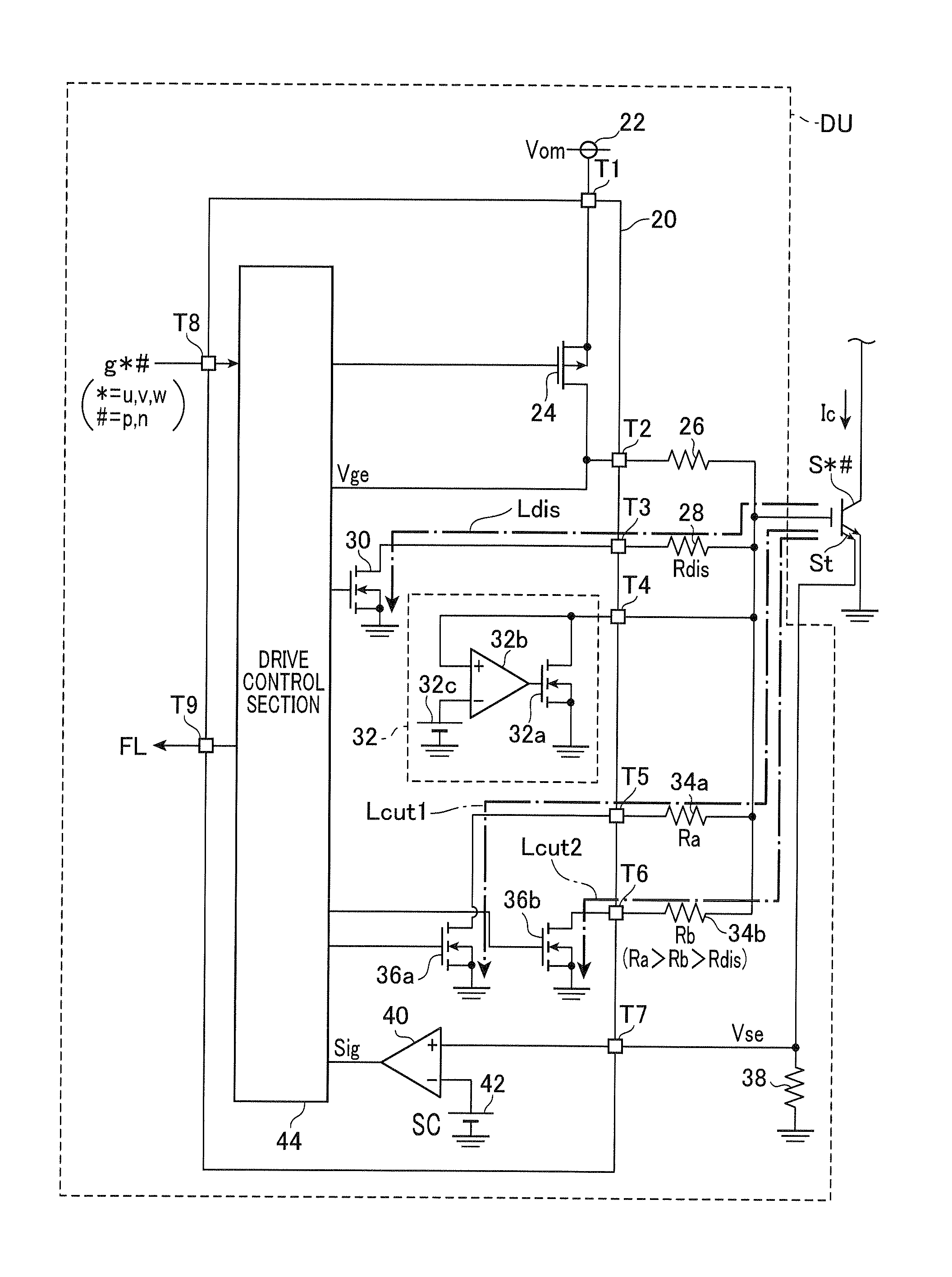
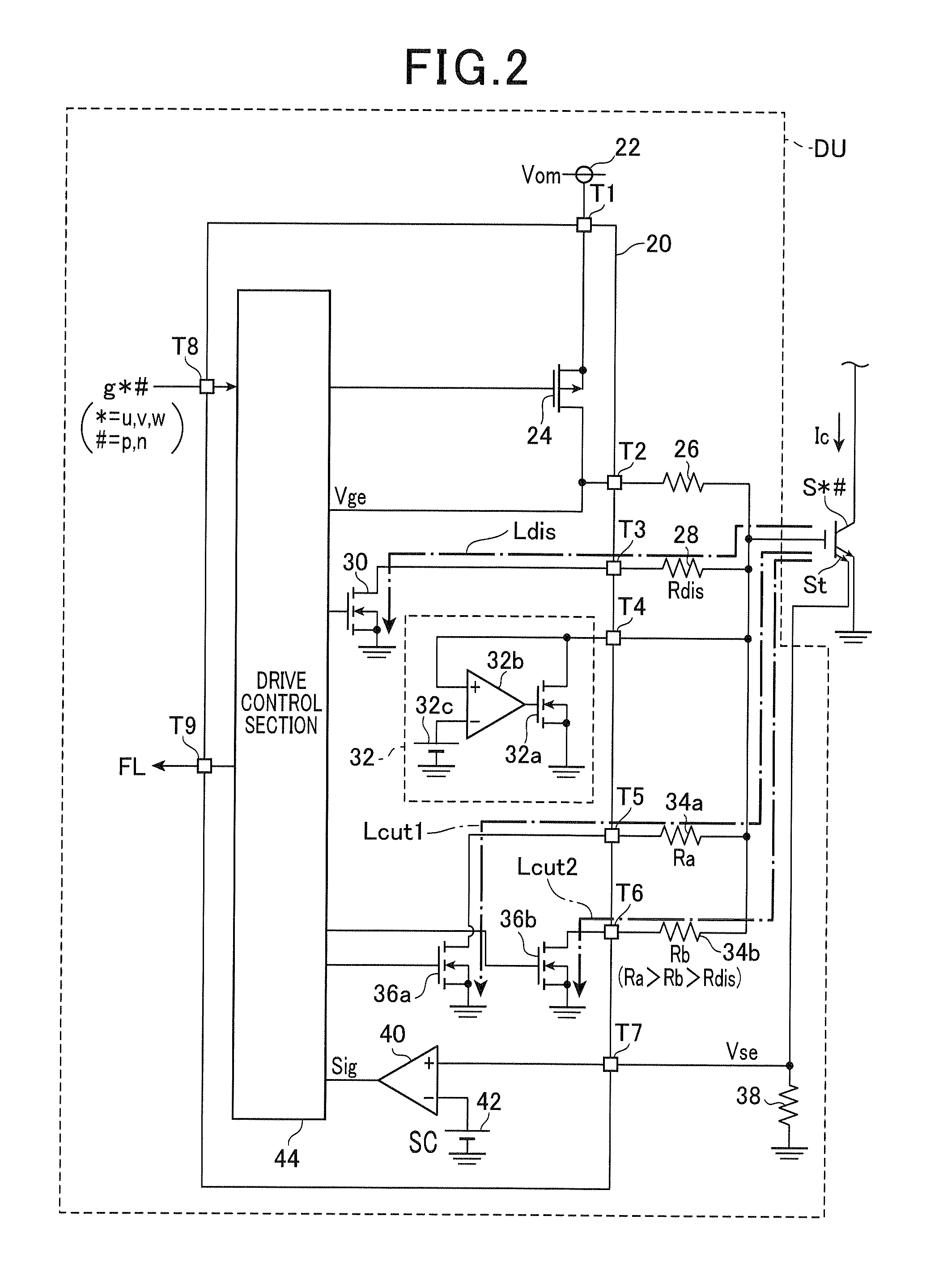
An inverter for driving a motor generator has series connection units, each of which has two switching elements, connected in series, in high and low voltage sides, respectively. A drive unit is arranged for each switching element. A gate of the switching element is connected to an emitter thereof through a first cutoff resistance and a first cutoff switching element in the drive unit. The gate of the switching element is also connected to the emitter thereof through a second cutoff resistance and a second cutoff switching element in the drive unit. A resistance value of the first cutoff resistance is higher than a resistance value of the second cutoff resistance. A software cutoff process is performed when the switching element is in a completely turned-on state so that the first cutoff switching element is turned on and the second cutoff switching element is turned off.

Description

CROSS-REFERENCE TO RELATED APPLICATION[0001]This application is related to and claims priority from Japanese Patent Application No. 2013-85237 filed on Apr. 15, 2013, the contents of which are hereby incorporated by reference.BACKGROUND OF THE INVENTION[0002]1. Field of the Invention[0003]The present invention relates to drive units having an overcurrent protection function for driving switching elements in an inverter, for example to be applied to motor generators, etc.[0004]2. Description of the Related Art[0005]There is a known technique, for example, patent document 1, Japanese patent No. 3367699, which has disclosed a conventional drive unit capable of driving a semiconductor switching element, for example composed of Insulated Gate Bipolar Transistors (IGBTs). The drive unit has an overcurrent protection function capable of decreasing a gate voltage of the semiconductor switching element when a collector current, which flows between an input terminal (the collector terminal) a...

Claims


Application Information

Patent Timeline
Patent Type & Authority Patents(United States)
IPC IPC(8): H02M1/32H02M1/08H03K17/082H03K17/16H02M7/5387H02M1/00
CPCH02M1/32H02M1/08H03K17/0828H03K17/163H03K17/168H02M7/5387
Inventor SUZUKI, TOMOTAKAHAMANAKA, YOSHIYUKI
Owner DENSO CORP
Learn More