
Battery with a sheathing member to prevent leakage of electrolytic solution

a technology of electrolytic solution and sheathing member, which is applied in the direction of cell components, cell component details, electrochemical generators, etc., can solve the problems of unavoidable leakage of electrolytic solution contained in the battery, the safety valve itself undergoes chronological deterioration, and the high probability of leakag

Inactive Publication Date: 2002-07-02
SONY CORP
View PDF7 Cites 9 Cited by
  • Summary
  • Abstract
  • Description
  • Claims
  • Application Information

AI Technical Summary

Benefits of technology

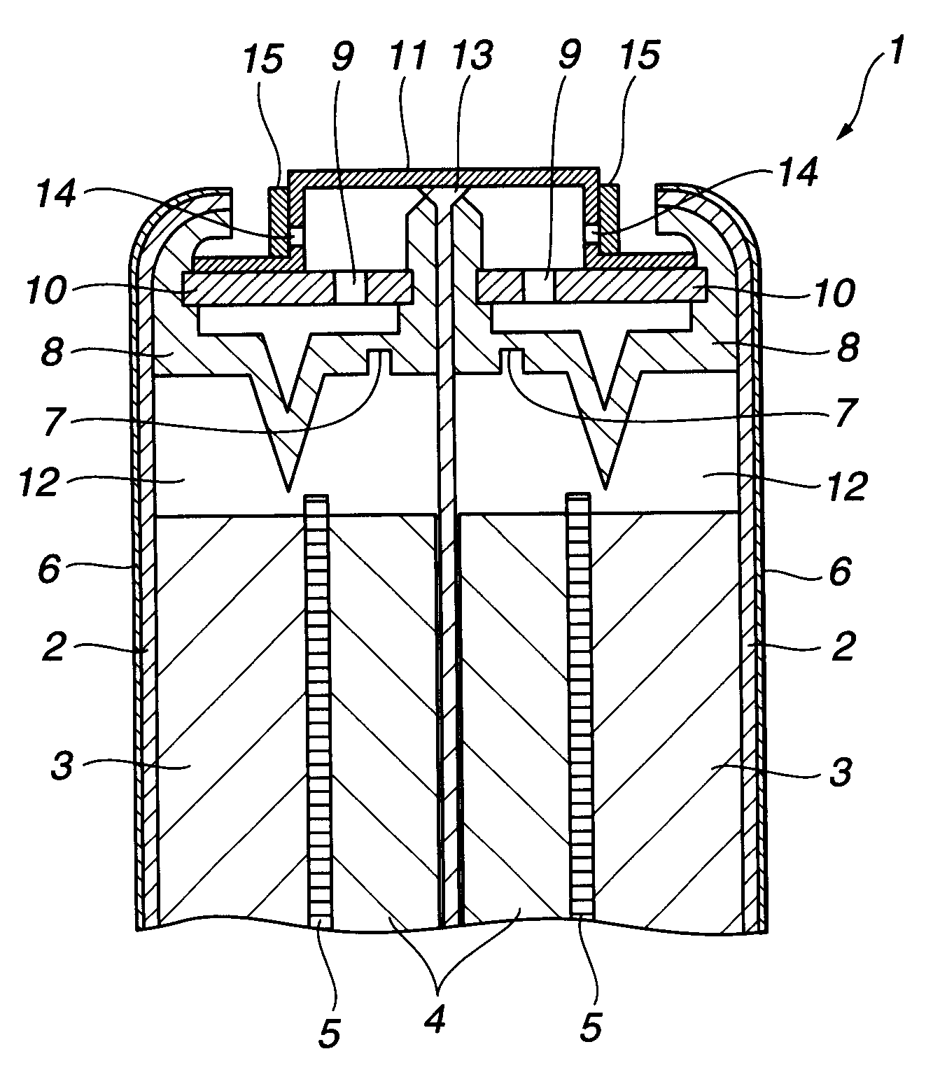
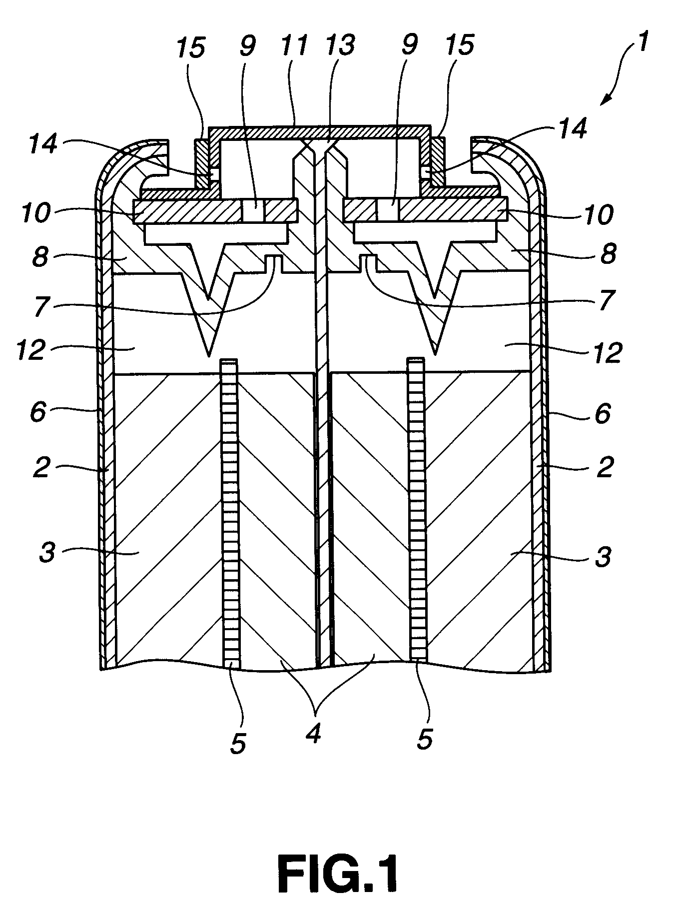
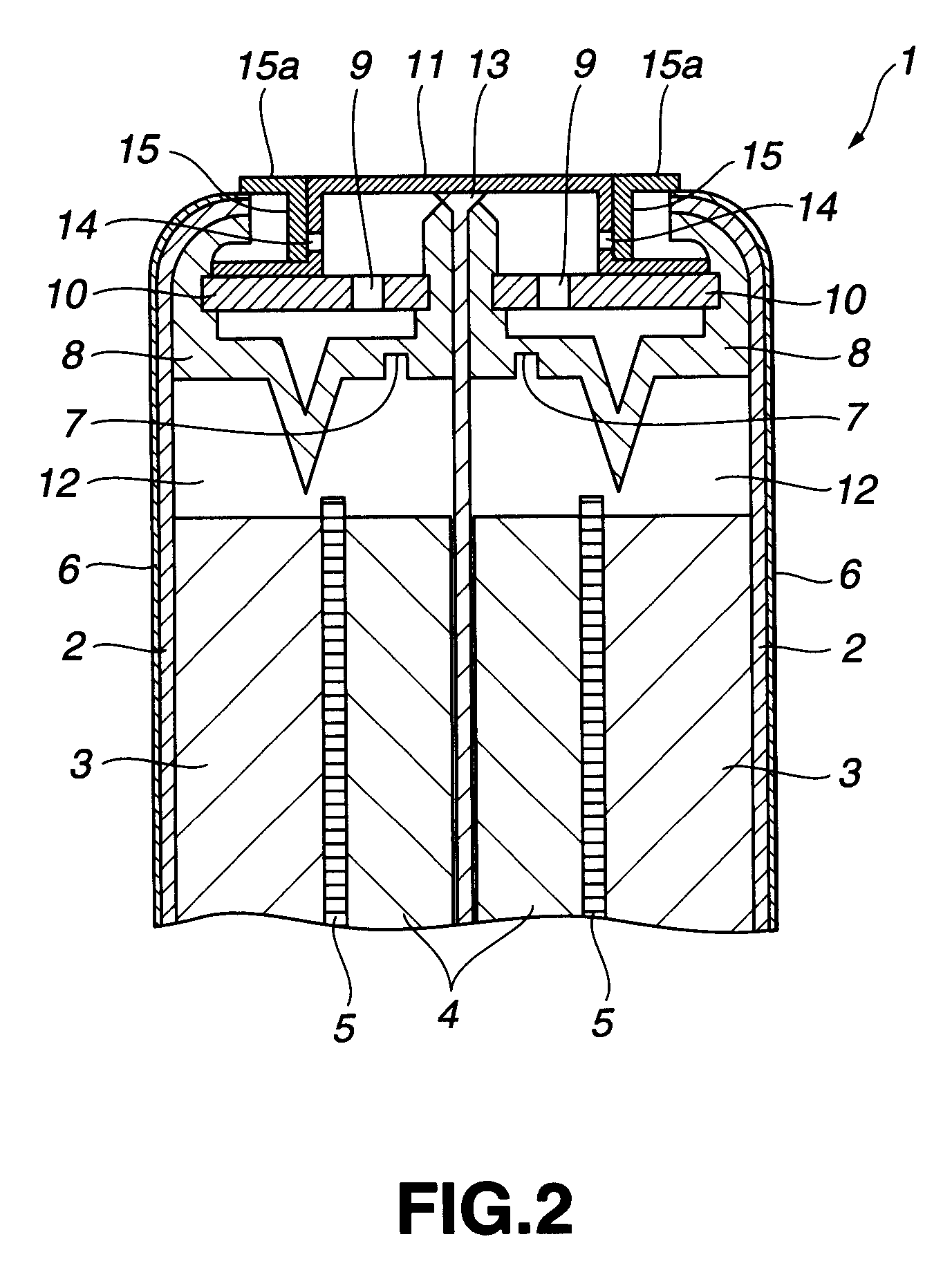
With the battery according to the present invention, in which the degassing hole formed in the battery lid is covered by the sheathing member to prevent the electrolytic solution from leaking through the degassing hole.
According to the present invention, the degassing hole formed in the battery case is covered by the sheathing member to prevent the leakage of the electrolytic solution through the degassing hole. Thus, the tubular battery of the present invention is extremely high in operational reliability.

Problems solved by technology

The alkaline battery having the safety valve had a drawback that, if the battery is allowed to stand for prolonged time at elevated temperature, the safety valve itself undergoes chronological deterioration, such that the safety valve is actuated even if the internal pressure in the battery is low.
If the safety valve is actuated, leakage of the electrolytic solution contained in the battery occurs unavoidably.
Should the leaking electrolytic solution be deposited e.g., on the skin, it is highly likely that the skin be thereby injured.
However, since this washer is not designed to completely cover the degassing hole of the negative terminal, it is not possible to prevent leakage of the electrolytic solution.
However, should chronological deterioration occur on prolonged storage under elevated temperatures, there are occasions where the safety valve 7 is actuated to release the battery internal pressure even if the internal pressure value is small.

Method used


Image

  • Battery with a sheathing member to prevent leakage of electrolytic solution
  • Battery with a sheathing member to prevent leakage of electrolytic solution
  • Battery with a sheathing member to prevent leakage of electrolytic solution

Examples


example 1

First, manganese dioxide, graphite and a 39%-aqueous solution of potassium hydroxide were mixed together homogeneously at a pre-set ratio to prepare a positive electrode mixture. 3.6 g of this positive electrode mixture was then provisionally molded to a ring shape with an outer diameter of 13.2 mm, an inner diameter of 9.1 mm and a height of 15.0 mm.

Three of provisionally molded positive electrode mixtures were inserted into the inside of the cylindrically-shaped positive electrode case 2, which then was pressured from above at a pressure of 1 ton / cm.sup.2.

Into the hollow portions between the positive electrode mixtures were inserted bottomed cylindrically-shaped separators, into which a 39%-aqueous solution of potassium hydroxide and the negative electrode mixture were charged. The opening portion of the positive electrode case was tightly sealed by a sealing unit to prepare a cylindrically-shaped alkaline battery.

A 6,6 nylon ring is loaded on the outer periphery of the negative e...

example 2

A cylindrically-shaped alkaline battery was prepared in the same way as in Example 1, except using a polypropylene ring as a ring mounted on the negative electrode,

example 3

A cylindrically-shaped alkaline battery was prepared in the same way as in Example 1, except using a ring of polyolefinic thermoplastic elastomer as a ring mounted on the negative electrode.


PUM

PropertyMeasurementUnit
heightaaaaaaaaaa
inner diameteraaaaaaaaaa

Abstract

A battery in which an electrolytic solution may be prevented from leakage. Within a battery case in the form of a bottomed tube, a positive electrode, a negative electrode and an electrolyte are arranged. An opening in the battery case is sealed by a battery lid having a degassing hole, which degassing hole is covered by a sheathing member.

Description

The present application claims priority to Japanese Application No. P11-306129 filed Oct. 27, 1999, which application is incorporated herein by reference to the extent permitted by law.1. Field of the InventionThis invention relates to a tubular-shaped battery.2. Description of Related ArtRecently, an increasing number of electronic equipment are reduced in size and portable and can be run by batteries such as alkaline cells. In general, in order to vent a gas occurred in a battery on incorrectly charging the battery, a safety valve is provided in a portion of a battery sealing element to release the internal pressure in safety at a time point when the internal pressure in the battery is low.The alkaline battery having the safety valve had a drawback that, if the battery is allowed to stand for prolonged time at elevated temperature, the safety valve itself undergoes chronological deterioration, such that the safety valve is actuated even if the internal pressure in the battery is l...

Claims


Application Information

Patent Timeline
Patent Type & Authority Patents(United States)
IPC IPC(8): H01M2/12H01M2/04H01M2/08
CPCH01M2/0421H01M2/1229Y02E60/10H01M50/154H01M50/325
Inventor OYA, KUNIYASU
Owner SONY CORP
Learn More