Bracket for attaching an electrical cable to a vehicle

a technology for attaching brackets and electrical cables, which is applied in the direction of machine supports, transportation and packaging, and other domestic objects, can solve the problems of easy loosening of cables, and achieve the effects of reducing relative movement, less slack, and low friction coefficien

Inactive Publication Date: 2016-11-29
AIRBUS OPERATIONS LTD
View PDF42 Cites 1 Cited by
  • Summary
  • Abstract
  • Description
  • Claims
  • Application Information

AI Technical Summary

Benefits of technology

[0012]In addition, the aviation fuel in the fuel tank acts as a lubricant and the over braid coating on the outside of the cable is made from a PEEK™ material, which has a low coefficient of friction. Hence, the cable can become loose very easily.
[0013]Providing a non-planar rear surface on the cable securing portion acts to fill the gap, meaning that the cable-tie has less slack in its loop. This allows the cable to be more firmly secured to the bracket by a cable-tie and reduces the relative movement between the bracket and the cable and prevents the cable from moving out of position.
[0014]In addition, with a prior art bracket, in the event of a cable-tie / bracket failure, the length of cable between the brackets either side of the failure is increased. This is due to the cable being loose in the bracket. This further adds to the undesirable “skipping rope” effect. This is unlikely to happen in the bracket of the present invention as the cable is much less able to move in the bracket and so the length of cable between the brackets either side of the failure is not increased. Hence, the “skipping rope” effect is limited to the effect produced by the amount of length between the brackets on installation. This increases the possible distance between the brackets and means less brackets have to be installed. This obviously saves time, money and weight.
[0017]Preferably, the path provided has a radius of curvature that does not exceed the natural minimum radius of curvature of the cable-tie. The applicant has realised that, in the prior art brackets, the areas of high curvature of the cable-tie at the edges of the rear of the cable mounting face can cause the cable-tie to stretch over time. This reduces the tension on the cable-tie and increases slack in the cable-tie loop. The natural minimum radius of curvature of the cable-tie can therefore be defined as the smallest radius of curvature of the cable-tie at which deformation of the cable-tie does not occur.
[0021]Preferably, the non-planar rear surface defines said at least three points of contact for the cable-tie on the path behind the cable abutment portion in more two transverse directions behind the cable abutment portion, thereby allowing the cable to be secured to the bracket in two directions transverse to each other.

Problems solved by technology

Hence, the cable can become loose very easily.

Method used


Image

  • Bracket for attaching an electrical cable to a vehicle
  • Bracket for attaching an electrical cable to a vehicle
  • Bracket for attaching an electrical cable to a vehicle

Examples


first embodiment

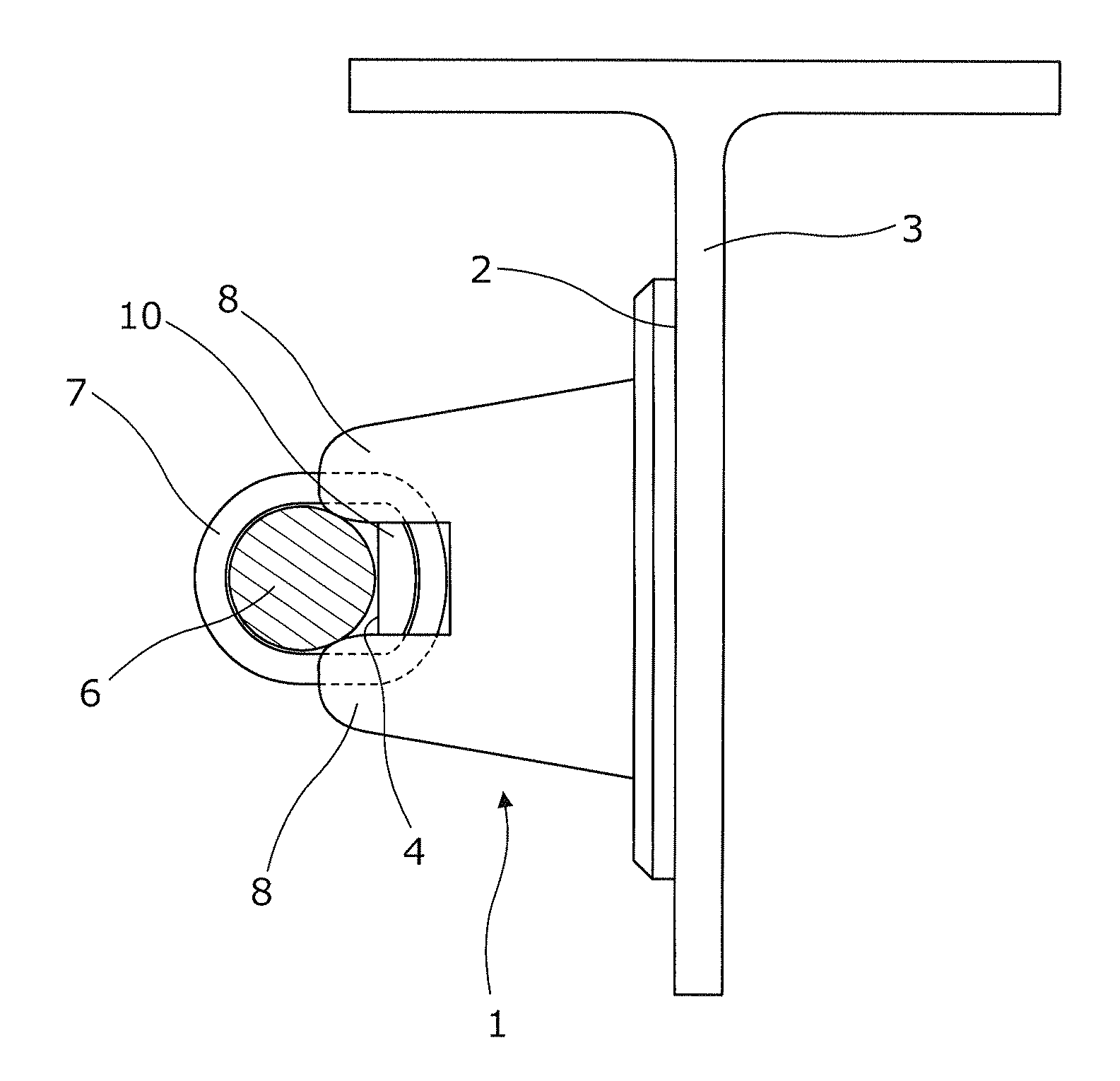
[0055]FIGS. 3a and 3b show a bracket 1 according to the invention. It is similar to the prior art bracket of FIGS. 1a and 1b. The bracket 1 has a flat bonding face 2 at one end for attaching to a stringer 3 of the fuel tank. At the opposite end, the bracket has a generally square shaped cable mounting face 4. On each corner of the mounting face 4 is a locating bump 8. These locating bumps 8 provide abutment surfaces for the cable 6 to rest on or against, thereby ensuring the cable rests in a certain position on the bracket 1. On each side of the square face is a slot 5 for a cable-tie. The cable 6 is secured to the cable mounting face 4 by a cable-tie 7 looped around the cable 6 and cable mounting face 4 through two opposite cable-tie slots 5.

[0056]However, an important difference between the bracket of FIGS. 3a and 3b and the bracket of FIGS. 1a and 1b is that the bracket of FIGS. 3a and 3b also comprises a nodule 10 on the back of the cable mounting face 4. The nodule is in the sh...

second embodiment

[0058]FIGS. 4a to 4d show a bracket 1 according to the invention. The bracket 1 is of a different shape to the bracket of FIGS. 3a and 3b.

[0059]The bracket 1 has a head portion 11 at one end of the bracket and an arm portion 12 extending from the head portion 11 to an end portion 13 at the other end of the bracket 1.

[0060]The head portion 11 comprises a flat bonding face 2 for attaching to a stringer 3 of the fuel tank using adhesive. The bonding face 2 has a thickness of 2 mm and is in the form of a round-cornered rectangle. The dimensions of the rectangle are 20 by 30 mm. On the other side of the face 2, on the short edges of the rectangle of the head portion 11, two sloping walls 14 extend upwards. The walls 14 have a thickness of 2 mm. The walls 14 are sloped such that their height from the face 2 increases as they move away, from the head portion end of the bracket 1.

[0061]At the end of the rectangle of the mounting face 2 nearest the arm portion 12, the sloping walls 14 curve...

third embodiment

[0076]FIG. 8 shows two brackets 1 according to the invention. The brackets 1 of FIG. 8 are of a different shape to the brackets of FIGS. 3a and 3b or FIGS. 4a to 7b.

[0077]Each bracket 1 of FIG. 8 has a head portion 31 at one end of the bracket and an arm portion 32 extending from the head portion 11 to an end portion 33 at the other end of the bracket 1.

[0078]The head portion 31 comprises a flat bonding face 2 for attaching to a stringer 3 of the fuel tank. The bonding face 2 has the form of a rounded rectangle. On the other side of the face 2, a rounded triangular-shaped arm 34 extends out from the bonding face 2. The rounded triangle is symmetrical and has its short side connected to a long edge of the rectangle of face 2. The two long sides of the triangle 34 form the outline of the arm portion 32.

[0079]Extending between the triangular arm 34 and the reverse of the bonding face 2 is a right-angled triangle-shaped flange 35. The shortest side of the triangle flange 35 is connecte...


PUM

PropertyMeasurementUnit
widthaaaaaaaaaa
widthaaaaaaaaaa
widthaaaaaaaaaa

Abstract

The invention provides a bracket 1 for attaching an electrical cable 6 to a vehicle, the bracket comprising a vehicle attachment portion 11, 31 for attaching the bracket to a vehicle attachment surface of the vehicle, and a cable securing portion 13, 33 for securing the cable to the bracket 1, the cable securing portion 13, 33 comprising a cable abutment portion 4, 8 against the front surface of which the cable 6 can be secured by a cable-tie 7 forming a closed loop around the cable 6 and cable abutment portion 4, 8, and a non-planar rear surface which at least partially defines the path of the closed loop of the cable-tie 7 behind the cable abutment portion 4, 8, the path passing a first region on one side of the non-planar rear surface and a second region on the opposite side of the non-planar rear surface, wherein, in use, the non-planar rear surface directly supports the cable-tie 7 at a third region along the path of the closed loop, the third region being positioned, along the path, between the first and second regions. The invention also provides an aircraft fuel tank comprising a plurality of such brackets 1 and an electrical cable 6, secured to each of the brackets with a cable-tie 7.

Description

[0001]This application claims priority to GB Application No. 1001002.3 filed 22 Aug. 2010, the entire contents of which is hereby incorporated by reference.BACKGROUND OF THE INVENTION[0002]The present invention concerns brackets for attaching an electrical cable to a vehicle. More particularly, but not exclusively, this invention concerns a bracket for attaching to a fuel tank of an aircraft in order to secure an electrical cable. The invention also concerns an electrical assembly comprising a plurality of such brackets, a fuel tank comprising a plurality of such brackets, an aircraft comprising a plurality of such brackets or such an electrical assembly or fuel tank and a method of attaching a cable to a vehicle.[0003]Such brackets are often used to securely hold electrical cable, which is part of a Fuel Quantity Indication (FQI) System of an aircraft. The cable has to be held within the aircraft fuel tank, generally contained within the wing of an aircraft. To comply with the elec...

Claims


Application Information

Patent Timeline
Patent Type & Authority Patents(United States)
IPC IPC(8): H02G3/00B64C1/40H02G3/32F16L3/08B60R16/02
CPCH02G3/32B60R16/0215B64C1/406Y02T50/46Y10T29/4995Y02T50/40
Inventor THOMAS, BRYAN
Owner AIRBUS OPERATIONS LTD
Why Eureka
Try Eureka