
Filter for a nuclear reactor containment ventilation system

a technology for containment ventilation and nuclear reactors, applied in nuclear engineering, nuclear elements, greenhouse gas reduction, etc., can solve the problems of contamination of the surrounding areas of damaged power plants, the containment vessel itself could fail, and the unsuitability for us

Active Publication Date: 2016-11-22
WESTINGHOUSE ELECTRIC CORP
View PDF27 Cites 4 Cited by
  • Summary
  • Abstract
  • Description
  • Claims
  • Application Information

AI Technical Summary

Problems solved by technology

However, it has been postulated that in severe accidents, the containment vessel itself could fail from gradually increasing pressure.
Although the likelihood of such an event is considered very small, the health risks associated with exposing the surrounding population to the radioactive releases of such an event has led many to believe that a mechanism should be provided to filter the gases and minimize the release of radioactivity, if the containment vessel is vented to reduce its pressure.
The nuclear accidents at Chernobyl, Ukraine in 1986 and more recently Fukushima Dai-ichi in Japan in 2011, clearly show the consequences of a release of fission products with long decay times. Large ground areas surrounding the damaged power plants were contaminated and rendered not suitable for use for several decades.
The cost impact is tremendous.

Method used


Image

  • Filter for a nuclear reactor containment ventilation system
  • Filter for a nuclear reactor containment ventilation system
  • Filter for a nuclear reactor containment ventilation system

Examples


Embodiment Construction

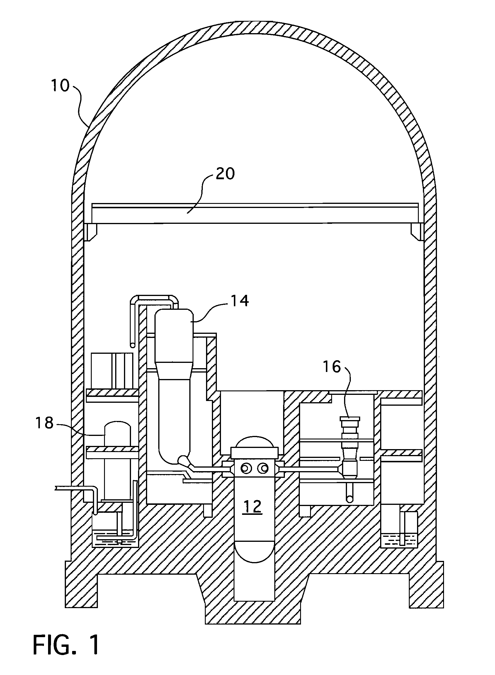
[0016]Referring to FIG. 1, there is schematically illustrated a pressurized water reactor nuclear power generating system including a containment building 10 (generally having a relatively thick outside concrete layer over a steel liner) which houses components of the nuclear reactor system, such as a reactor vessel 12, a steam generator 14, a reactor coolant pump 16, an accumulator tank 18 and overhead polar crane 20. Since all of these components and their relationships are well known and further, since they do not specifically cooperate, structurally or functionally, with the invention, they are not described or illustrated in greater detail. While the preferred embodiment of the invention is described in connection with a pressurized water reactor, it is to be understood that the system, in accordance with the invention as claimed hereafter, is equally applicable to nuclear reactors of any other design, such as, for example, a boiling water reactor or a gas reactor.

[0017]A filte...


PUM


Abstract

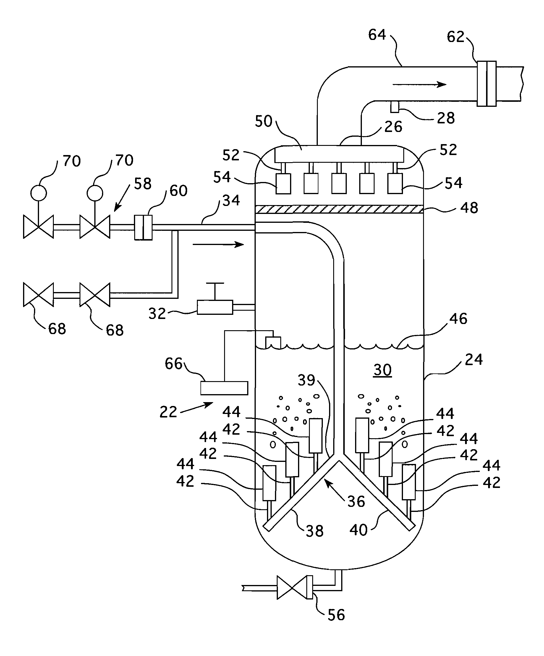
A wet filter for a nuclear reactor primary containment vent that employs an inclined manifold having a plurality of outlets that communicate through a first set of metal fiber filters submerged in a pool of water enclosed within a pressure vessel. A demister suspended above the pool of water to remove any entrained moisture in the filtered effluent before being passed through a second stage of higher density, dry, metal fiber filters connected to a second manifold that communicates with an outlet on the pressure vessel that is connected to an exhaust passage to the atmosphere.

Description

CROSS REFERENCE TO RELATED APPLICATION[0001]This application claims priority under 35 U.S.C. §119(e) to U.S. Provisional Application Ser. No. 61 / 668,585, filed Jul. 6, 2012, entitled “Wet Scrubber Using Fiber Filters for PWR and BWR Containment Venting.”BACKGROUND[0002]1. Field[0003]This invention pertains generally to nuclear reactor containment ventilation systems and more particularly to a wet filter for such systems.[0004]2. Related Art[0005]In many jurisdictions, nuclear power plants must be designed to ensure that even in the event of accidents, a mechanism will be provided to prevent or minimize the escape of radioactive material and noble gases. To guard against radioactive releases, the reactor system is typically housed within a primary containment structure that is constructed from steel and reinforced concrete. The primary containment vessel is designed to be capable of withstanding large pressures which may result from various accident scenarios. However, it has been po...

Claims


Application Information

Patent Timeline
Patent Type & Authority Patents(United States)
IPC IPC(8): G21C19/303G21F9/02G21C13/10G21C19/00G21C13/02G21C9/008
CPCG21C19/00G21C13/022G21C13/10G21C19/303G21F9/02G21C9/008Y02E30/40G21C9/004Y02E30/30
Inventor NILSSON, PER-OLOF
Owner WESTINGHOUSE ELECTRIC CORP
Learn More