Controller for variable valve mechanism

a variable valve and valve mechanism technology, applied in the direction of electric control, machines/engines, output power, etc., can solve the problem of easy cause of torque fluctuation due to a change in engine output, and achieve the effect of reducing the lift amount of the intake valve and reducing the possibility of torque fluctuation

Active Publication Date: 2016-11-22
TOYOTA JIDOSHA KK
View PDF5 Cites 0 Cited by
  • Summary
  • Abstract
  • Description
  • Claims
  • Application Information

AI Technical Summary

Benefits of technology

[0021]In the internal combustion engine in which external EGR is returned into the cylinders, at the time of returning from the cylinder deactivation mode, when some of the intake air flowing into the activated cylinders also flows into the returned cylinders, which have returned from the cylinder deactivation mode, some of the external EGR flowing into the activated cylinders also flows into the returned cylinders. Therefore, an external EGR amount flowing into the activated cylinders is changed and a combustion state of the activated cylinders is changed, so that the torque fluctuation may be also generated because of it. In this respect, in the above described configuration, the reduction in the intake air to the activated cylinders immediately after returning from the cylinder deactivation mode is suppressed by performing the above described overlap adjustment processing. Thus, a change in the external EGR amount flowing into the activated cylinders can also be suppressed. Therefore, immediately after returning from the cylinder deactivation mode, the generation of the torque fluctuation due to the change in the external EGR amount flowing into the cylinders is suppressed.

Problems solved by technology

When an internal combustion engine returns from a cylinder deactivation mode to an all-cylinder operation mode, torque fluctuation due to a change in the engine output is easily caused.

Method used


Image

  • Controller for variable valve mechanism
  • Controller for variable valve mechanism
  • Controller for variable valve mechanism

Examples


Embodiment Construction

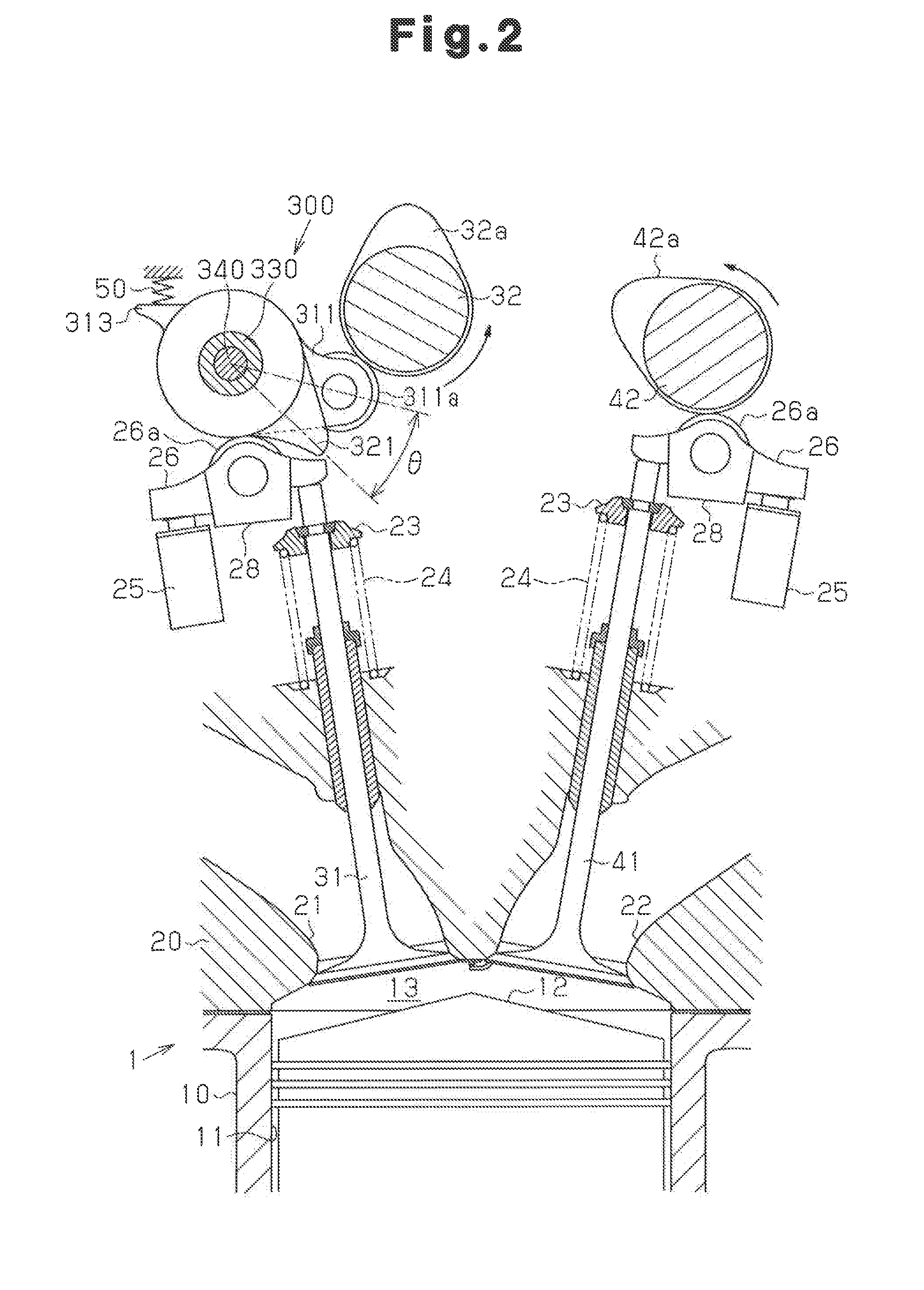
[0038]Hereinafter, a controller for a variable valve mechanism according to one embodiment will now be described with reference to FIGS. 1 to 10. The controller is applied to an inline four engine.

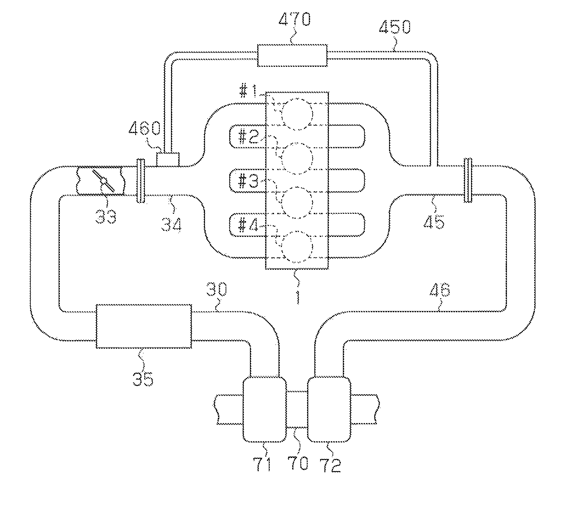
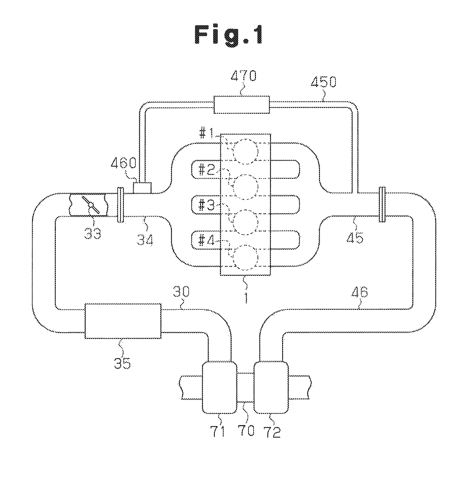
[0039]As shown in FIG. 1, an engine 1 has four cylinders including a first cylinder #1, a second cylinder #2, a third cylinder #3, and a fourth cylinder #4, which are provided in series.

[0040]The engine 1 has fuel injection valves for injecting fuel to the cylinders. An intake manifold 34 for admitting intake air to the cylinders and an exhaust manifold 45 for discharging exhaust gas from the cylinders are connected to the engine 1.

[0041]The intake manifold 34 is connected to an intake passage 30. A throttle valve 33 for adjusting an intake air amount is provided in the intake passage 30.

[0042]The exhaust manifold 45 is connected to an exhaust gas passage 46.

[0043]The engine 1 has a turbocharger 70, which is a forced induction device for supercharging intake air by utilizing the exhaust ga...


PUM


Abstract

An internal combustion engine includes a plurality of cylinders, intake valves (31) provided respectively in the cylinders, and a variable valve mechanism (600) for changing a valve characteristic of the intake valves (31). A motor (210) drives the variable valve mechanism (600). A motor controller (150) controls the motor (210). The internal combustion engine can be operated in a cylinder deactivation mode for retaining the intake valves (31) of some of the cylinders in a valve closing state. When the internal combustion engine returns from the cylinder deactivation mode, the motor controller (150) executes overlap adjustment processing for controlling the valve characteristic such that valve opening periods of the intake valves (31) are not overlapped between the cylinders.

Description

CROSS-REFERENCE TO RELATED APPLICATIONS[0001]This application is a national phase application of International Application No. PCT / JP2013 / 060081, filed Apr. 2, 2013, the content of which is incorporated herein by reference.TECHNICAL FIELD[0002]The present invention relates to a controller for a variable valve mechanism.BACKGROUND ART[0003]An internal combustion engine has been known that deactivates cylinders by stopping an opening and closing action of intake valves in some of the cylinders and maintaining a valve closing state during an engine operation, that is, performs cylinder deactivation.[0004]When an internal combustion engine returns from a cylinder deactivation mode to an all-cylinder operation mode, torque fluctuation due to a change in the engine output is easily caused.[0005]Therefore, for example, the internal combustion engine described in Patent Document 1 reduces the lift amount of intake valves at the time of returning from the cylinder deactivation mode to decrea...

Claims


Application Information

Patent Timeline
Patent Type & Authority Patents(United States)
IPC IPC(8): F02D13/02F02D41/00
CPCF02D13/0223F02D13/0261F02D41/0087Y02T10/18F02D13/023F02D13/06F01L1/185F01L1/2405F01L1/267F01L13/0005F01L13/0063F01L2013/001F01L2013/103F02D2041/001F02D2041/0012F02D2250/21F01L2305/00Y02T10/12
Inventor HIOKA, EIICHI
Owner TOYOTA JIDOSHA KK
Why Eureka
Try Eureka