Motor and brush configuration method
- Summary
- Abstract
- Description
- Claims
- Application Information
AI Technical Summary
Benefits of technology
Problems solved by technology
Method used
Image

Examples
first embodiment
[0079]A wiper motor according to a first embodiment of the present invention will now be discussed with reference to the drawings.
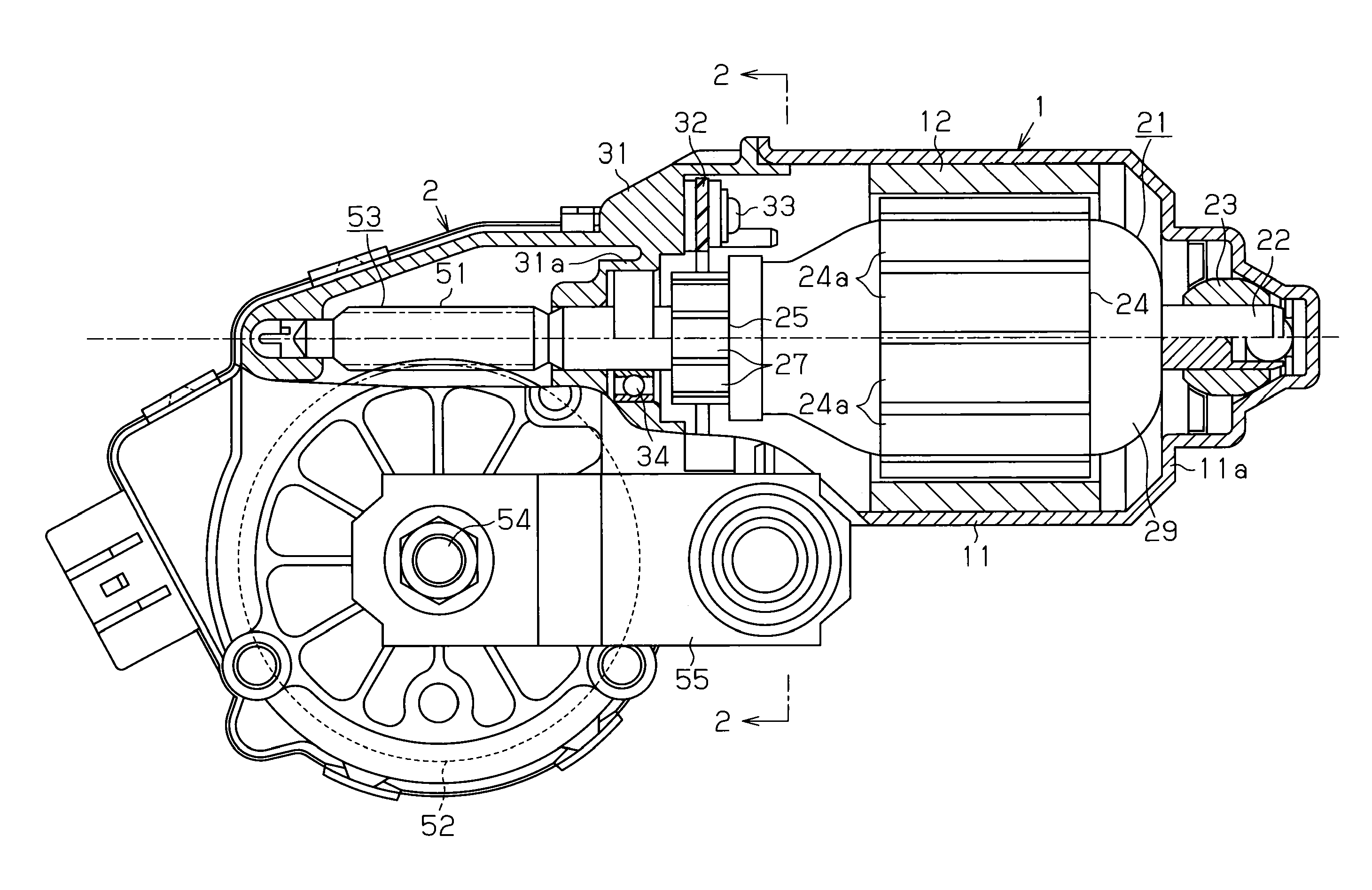
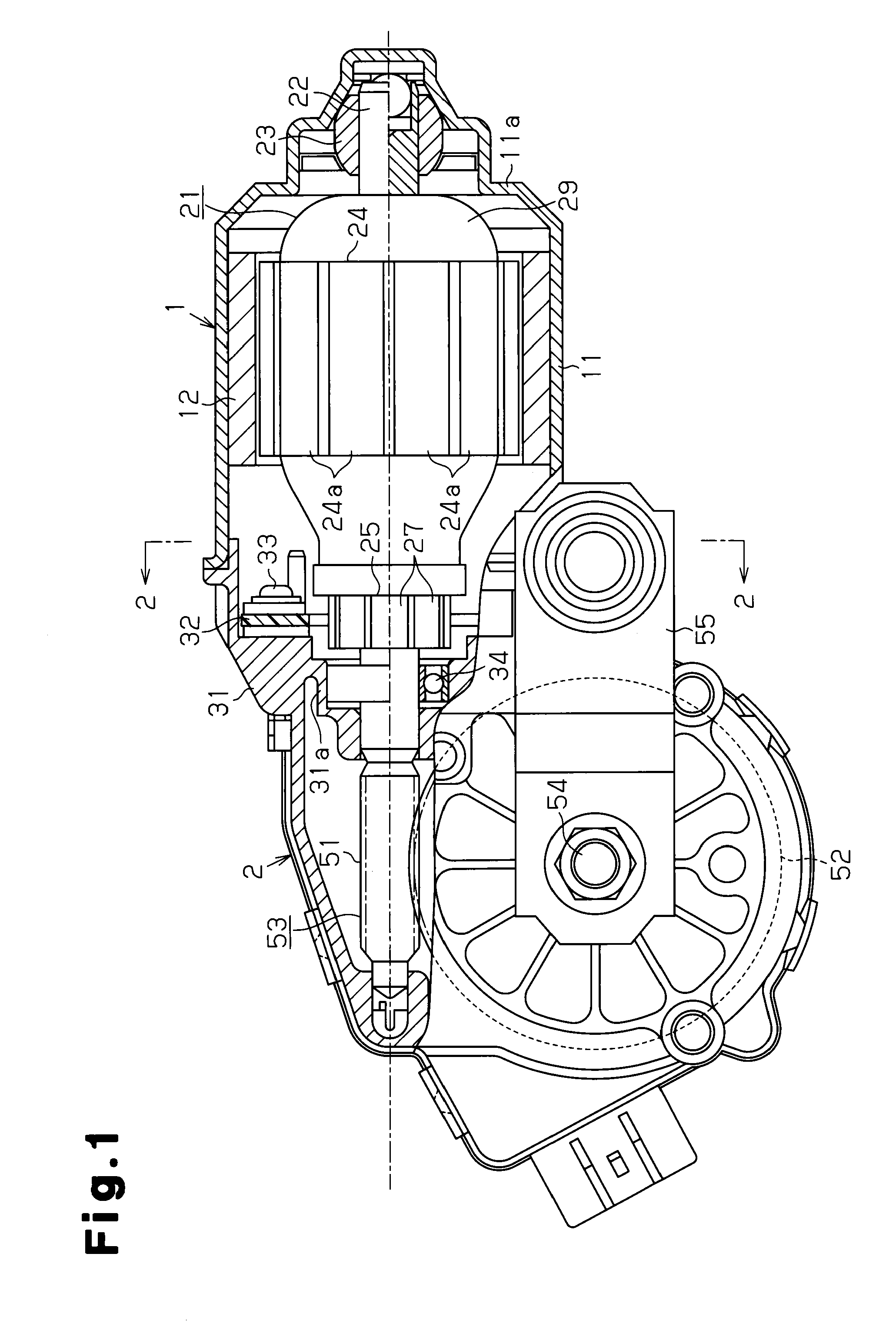
[0080]FIG. 1 is a schematic diagram showing a wiper motor of the present embodiment. The wiper motor is used as a drive source for a vehicle wiper (not shown), which wipes the windshield or the like of a vehicle, and includes a motor unit 1 and a reduction gear 2 coupled to the motor unit 1.
[0081]The motor unit 1 includes a tubular yoke housing 11 having a bottom 11a. At least one magnet 12 forming four magnetic pole portions (two N poles and two S poles) is fixed to an inner circumferential surface of the yoke housing 11. Thus, the motor unit 1 includes two magnetic circuits. The N poles and the S poles of the magnet 12 are alternately arranged in the circumferential direction of the yoke housing 11.
[0082]An armature 21 is rotatably arranged at a radially inner side of the magnet 12. The armature 21 includes a rotation shaft 22, an armature core 24, and ...
second embodiment
[0107]A wiper motor according to a second embodiment of the present invention will now be discussed with reference to the drawings. In the second embodiment, like or same reference numerals are given to those components that are the same as the corresponding components of the first embodiment. Such components will not be described.
[0108]FIG. 7 is a schematic diagram in which a motor unit and power supply brushes of the second embodiment are laid out along a plane. As shown in FIG. 7, the wiper motor of the second embodiment has a motor unit 61 including a yoke housing 11, which is similar to that of the motor unit 1 in the first embodiment, and at least one magnet forming four magnetic pole portions (two N poles and two S poles) fixed to an inner circumferential surface of the yoke housing 11 (refer to FIG. 1). An armature 62 is rotatably arranged at a radially inner side of the magnet 12. The armature 62 includes a rotation shaft 22, an armature core 63, which is fixed to the rotat...
third embodiment
[0130]A wiper motor according to a third embodiment of the present invention will now be discussed with reference to the drawings. In the third embodiment, like or same reference numerals are given to those components that are the same as the corresponding components of the first embodiment. Such components will not be described.
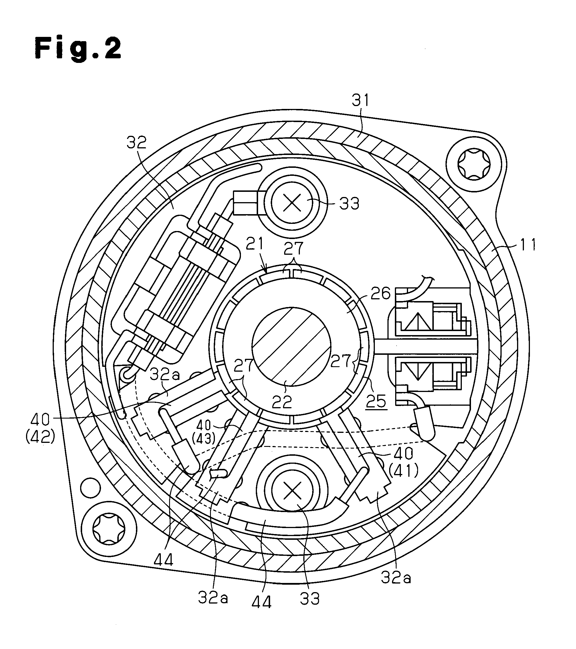
[0131]FIG. 10 is a schematic diagram in which a motor unit and power supply brushes of the third embodiment are laid out along a plane. As shown in FIG. 10, in the third embodiment, a brush holder 32 (refer to FIG. 2) of the reduction gear 2 holds six power supply brushes 80, each having the form of a tetragonal rod extending in the radial direction. Among the six power supply brushes 80, two are common brushes 81, two are low-speed drive brushes 82, and the remaining two are high-speed drive brushes 83. As shown in FIG. 13(a), the six power supply brushes 80 are arranged in the order of the common brush 81, the high-speed drive brush 83, and the low-speed d...
PUM
 Abstract
Description
Claims
Application Information
 - R&D
- Intellectual Property
- Life Sciences
- Materials
- Tech Scout
- Unparalleled Data Quality
- Higher Quality Content
- 60% Fewer Hallucinations
Browse by: Latest US Patents, China's latest patents, Technical Efficacy Thesaurus, Application Domain, Technology Topic, Popular Technical Reports.
© 2025 PatSnap. All rights reserved.Legal|Privacy policy|Modern Slavery Act Transparency Statement|Sitemap|About US| Contact US: help@patsnap.com