
Touch panel and operation method thereof

a technology of touch panel and operation method, which is applied in the field of touch panel, can solve the problems of difficult to reduce the size of the touch panel and complicated manufacturing methods, and achieve the effect of reducing the thickness of the touch panel

Active Publication Date: 2016-11-15
TPK TOUCH SOLUTIONS (XIAMEN) INC
View PDF18 Cites 0 Cited by
  • Summary
  • Abstract
  • Description
  • Claims
  • Application Information

AI Technical Summary

Benefits of technology

[0007]The present invention therefore provides a touch panel with a novel electrode structure, which is able to reduce the stacking layers of the touch panel.
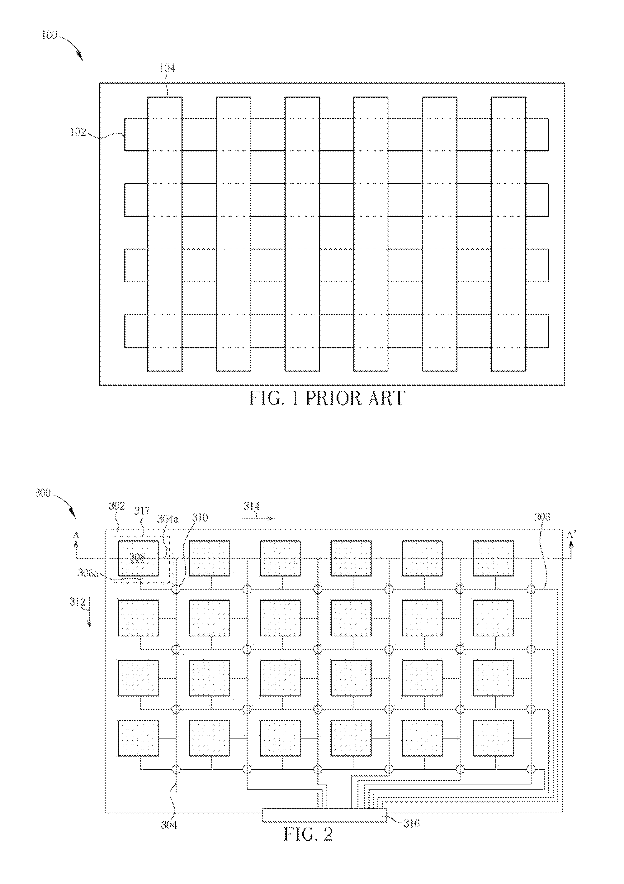
[0010]Since the touch panel in the present invention provides a novel electrode structure, only one layer of sensing electrode (the sensing pad) is required in the touch panel. In comparison with conventional arts, which require at least two layers of sensing electrode, the thickness of the touch panel can be reduced.

Problems solved by technology

The size of the touch panel is therefore hard to be smaller, and the manufacturing method may be complicated.

Method used


Image

  • Touch panel and operation method thereof
  • Touch panel and operation method thereof
  • Touch panel and operation method thereof

Examples


Embodiment Construction

[0020]For those skilled in the art to understand this invention, numerous embodiments are described below, annexing drawings to minutely illustrate the matters of the invention and the purpose thereof.

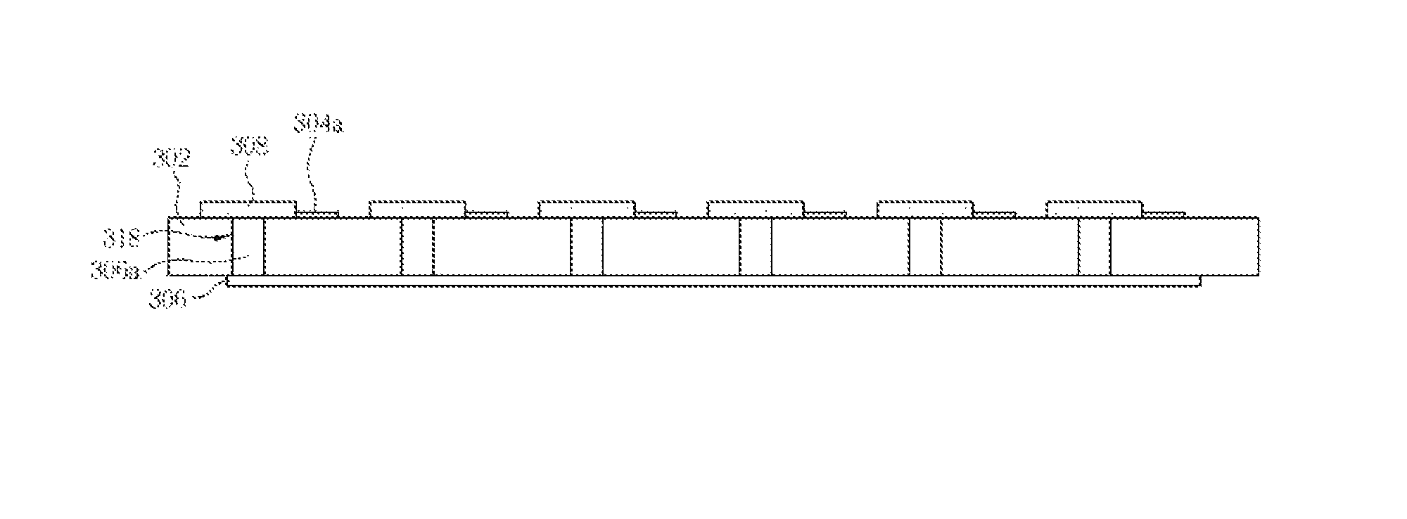
[0021]FIG. 2, illustrates a schematic diagram of the touch panel according to the first embodiment in the present invention. As shown in FIG. 2, the touch panel 300 in the present embodiment includes a substrate 302 in which a plurality of first traces 304, a plurality of second traces 306, a plurality of sensing pads 308, and a plurality of insulation mounds 310 are disposed on the substrate 302. In the present embodiment, the first traces 304, the second traces 306, the sensing pads 308, and the insulation mound 310 are disposed on the same side of the substrate 302. In one embodiment, the substrate 302 may be any flexible transparent substrate or any rigid transparent substrate, such as a glass substrate, a plastic substrate, or a quartz substrate.

[0022]As shown in FIG. 2, the first...


PUM


Abstract

The present invention relates to a touch panel. The touch panel includes a substrate, a plurality of first traces, a plurality of second traces, and a plurality of sensing pads. The first traces are disposed on the substrate and are parallel to each other along a first direction. The second traces are disposed on the substrate and are parallel to each other along a second direction. The first traces and the second traces interlace with each other to form a plurality of sensing pad areas. Each sensing pad is disposed in each sensing pad area, and is electrically connected to each first trace and each second trace. The present invention further provides a method of operating the same. In the present invention, the thickness of the touch panel is decreased, and the material for the electrodes is economized. Consequently, the costs of the touch panel can be reduced.

Description

[0001]This application claims the benefit of China application No. 201110225224.9, filed on Jul. 28, 2011.BACKGROUND OF THE INVENTION[0002]1. Field of the Invention[0003]The present invention relates to a touch panel, and more particularly, to a touch panel with a novel electrode structure.[0004]2. Description of the Prior Art[0005]Currently, in the market of various kinds of consumer electronic products, touch panels have been widely applied to portable electronic devices such as personal digital assistants (PDA), mobile phones, notebooks, and even in personal computers and digital home appliances for serving as the interface of an information communication tool between the users and the electronic devices. When using the touch panel, the user can directly operate and send out a command through the objects displayed on the panel, thus providing a more user-friendly interface. With the pursuit of electronic products of compact size in the market, touch panel has gradually replaced c...

Claims


Application Information

Patent Timeline
Patent Type & Authority Patents(United States)
IPC IPC(8): G09G5/00G06F3/044G06F3/045
CPCG06F3/044G06F3/045G06F3/0445G06F3/0446G02F1/13338G06F3/041G06F2203/04103
Inventor DING, HUAYU, SILU
Owner TPK TOUCH SOLUTIONS (XIAMEN) INC
Learn More