
Hydraulic apparatus

Active Publication Date: 2016-11-15
SAFIM
View PDF23 Cites 2 Cited by
  • Summary
  • Abstract
  • Description
  • Claims
  • Application Information

AI Technical Summary

Benefits of technology

Enables continued vehicle control under emergency conditions by supplying sufficient pressurized oil to steering servo controls, reducing driver effort and preventing damage from excessive oil pressure, while minimizing costs and energy consumption.

Problems solved by technology

In addition to the above, if the pumping parts are set to supply several working apparatus mounted on the vehicle and they require different oil pressures, it could happen that the servo controls that operate the steering parts are sent oil at a pressure that is too high which could damage them: thus, it is necessary to mount an additional pressure compensating device that limits the pressure of the oil sent to the servo controls that operate the steering parts, e.g. by reducing the flow of oil.

Method used


Image

  • Hydraulic apparatus
  • Hydraulic apparatus
  • Hydraulic apparatus

Examples


Embodiment Construction

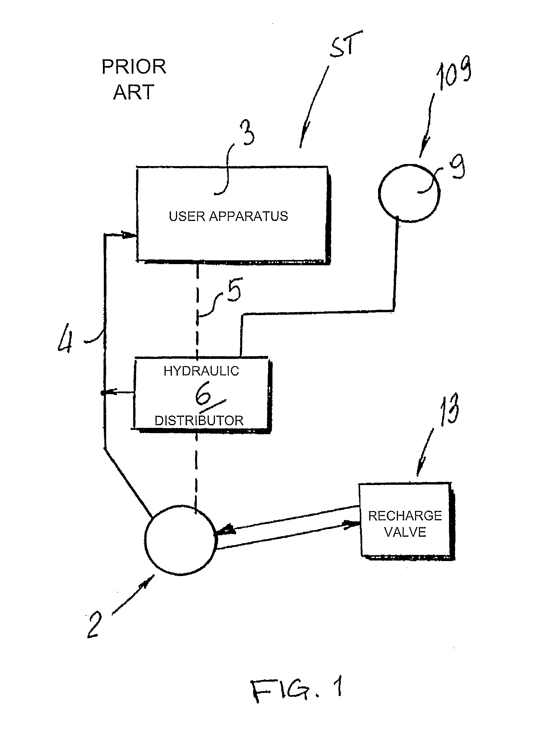
[0035]With reference to FIG. 1, ST indicates a known hydraulic user apparatus, hereinafter referred to briefly as user apparatus ST like, e.g., the hydrostatic power steering 3 of a work vehicle, more specifically an agricultural tractor.

[0036]The user apparatus ST is supplied by a pump 2, designed to pump oil at a first pressure “P” towards the hydrostatic power steering 3.

[0037]The pump 2 is connected to the hydrostatic power steering 3 by means of a hydraulic circuit indicated in its totality with 4 in the Figures and between the hydrostatic power steering 3 and the pump 2 a line is contemplated for measuring pressures, known by the name of “load sensing line”, in this case “load or pressure value” indicated with 5 and is able to transmit to the pump 2 pressure value variations which occur inside the hydrostatic power steering 3 when it is operated by the driver when he / she has to turn the steering wheel.

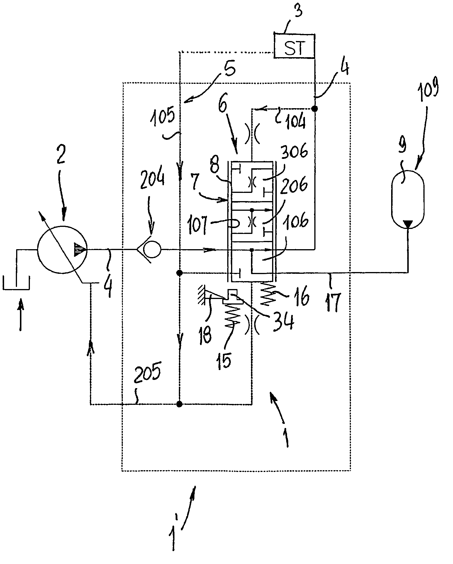
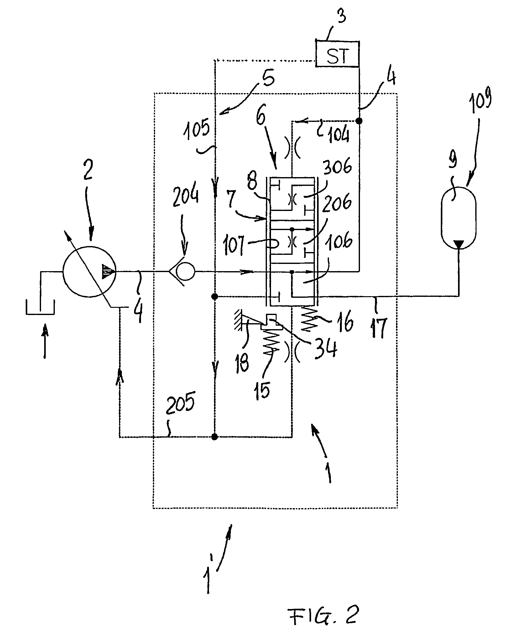
[0038]With reference to FIGS. 2 to 5, a hydraulic apparatus 1 is illustrated...


PUM


Abstract

The hydraulic apparatus includes: at least a pumping device for pumping a fluid at a first pressure; at least a user device of the fluid at the first pressure; at least an emergency supply device connectable to the user device activating a connection; at least an activation device of the connection that can be operated at a second pressure of the fluid different from the first pressure and interposed between the user device and the emergency supply device, the activation device having an emergency configuration wherein both the pumping device and the emergency supply device are connected to the user device.

Description

CROSS REFERENCE TO RELATED APPLICATIONS[0001]This application is the National Stage of PCT / IB2008 / 000576 filed on Mar. 13, 2008, which claims priority under 35 U.S.C. §119 of Italian Application No. MO2007A000097 filed on Mar. 20, 2007. The international application under PCT article 21(2) was published in English.TECHNICAL FIELD[0002]The invention relates to a hydraulic apparatus, suitable for distributing pressurised fluid in a hydraulic circuit of a work vehicle also under emergency conditions.BACKGROUND ART[0003]In work vehicles, used for working both on the fields and worksites, the laws that refer to safety require that such vehicles can be controlled even if the hydraulic units are damaged that take pressurised oil to the various driving and working apparatus on the vehicle.[0004]To be able to keep the vehicle under control at all times, the pressurised oil, supplied by a pumping unit, is distributed by suitable hydraulic distributors that see to sending the correct quantitie...

Claims


Application Information

Patent Timeline
Patent Type & Authority Patents(United States)
IPC IPC(8): B62D5/30F15B1/02E02F9/22F15B20/00
CPCF15B1/022B62D5/30E02F9/225E02F9/226E02F9/2217E02F9/2267F15B20/005F15B2211/20523F15B2211/20553F15B2211/212F15B2211/6052F15B2211/625F15B2211/863F15B2211/8752
Inventor MAMEI, ENRICOMAMEI, ERONNEMAMEI, OMER
Owner SAFIM
Learn More