Vehicle control device

a vehicle control and control device technology, applied in the direction of battery/fuel cell control arrangement, battery/cell propulsion, transportation and packaging, etc., can solve the problems of lowering engine output, ineffective control performed by the above described vehicle control device, and inability to change the soc of the electricity storage device, etc., to prevent the energy generated by regenerative braking

Active Publication Date: 2016-11-01
TOYOTA JIDOSHA KK
View PDF4 Cites 0 Cited by
  • Summary
  • Abstract
  • Description
  • Claims
  • Application Information

AI Technical Summary

Benefits of technology

[0009]In a normal driving environment, control of the vehicle increases electricity consumption before the vehicle reaches a predicted regeneration zone. In contrast, in a driving environment with a low air density, the output of the motor may be increased for compensating for the output of the internal combustion engine or the power of the internal combustion engine that is used for generating electricity using the motor may be insufficient. This can lower the remaining battery level to a level below the permissible range. Thus, in the above described configuration, in a case in which a predicted regeneration zone exists within a predetermined travel distance from the vehicle, if the air density, which is determined based on the air density determination value, is relatively low, either the target value of the remaining battery level is prohibited from being set to the corrected target value for increasing the electricity consumption before reaching the predicted regeneration zone or the engine and the motor are prohibited from being controlled based on the corrected target value. This restrains the remaining battery level from falling below the permissible range, so that the remaining battery level is properly adjusted in accordance with the driving environment.
[0011]With this configuration, even if the air density, which is determined based on the air density determination value, is relatively low, the target value of the remaining battery level is lowered if a predicted regeneration zone exists within the predetermined travel distance from the position of the vehicle. At this time, the target value is set to a value higher than a corrected target value that is set when a predicted regeneration zone exists and the air density is relatively high. Thus, the configuration prevents remaining battery level from falling below the permissible range while improving the fuel efficiency by consuming electricity before the vehicle reaches the predicted regeneration zone.
[0013]With this configuration, since the target value varies in accordance with the air density, the remaining battery level is restrained from falling below the permissible range while being adapted to be suitable for changes in the driving environment.
[0015]With this configuration, since the air density determination value is calculated by using a physical quantity that is a variation factor of the air density, the accuracy of the air density determination value is increased. Thus, the target value of the remaining battery level is set properly.
[0017]With this configuration, if the target value has not been changed when the vehicle reaches a predicted regeneration zone, the target value is maintained. The corrected target value, which has been set before the vehicle reaches the predicted regeneration zone, is returned to the standard target value. This prevents the energy generated by the regenerative braking from being converted into heat and lost.

Problems solved by technology

However, when a hybrid vehicle travels at high altitudes, such as in mountains, low air densities in such driving environments result in lowered engine output, and the SOC of the electricity storage device may not change as predicted by the above described control device.
Thus, the control performed by the above described vehicle control device is not necessarily effective.
In a normal driving environment, control of the vehicle increases electricity consumption before the vehicle reaches a predicted regeneration zone.
In contrast, in a driving environment with a low air density, the output of the motor may be increased for compensating for the output of the internal combustion engine or the power of the internal combustion engine that is used for generating electricity using the motor may be insufficient.

Method used


Image

  • Vehicle control device
  • Vehicle control device
  • Vehicle control device

Examples


Embodiment Construction

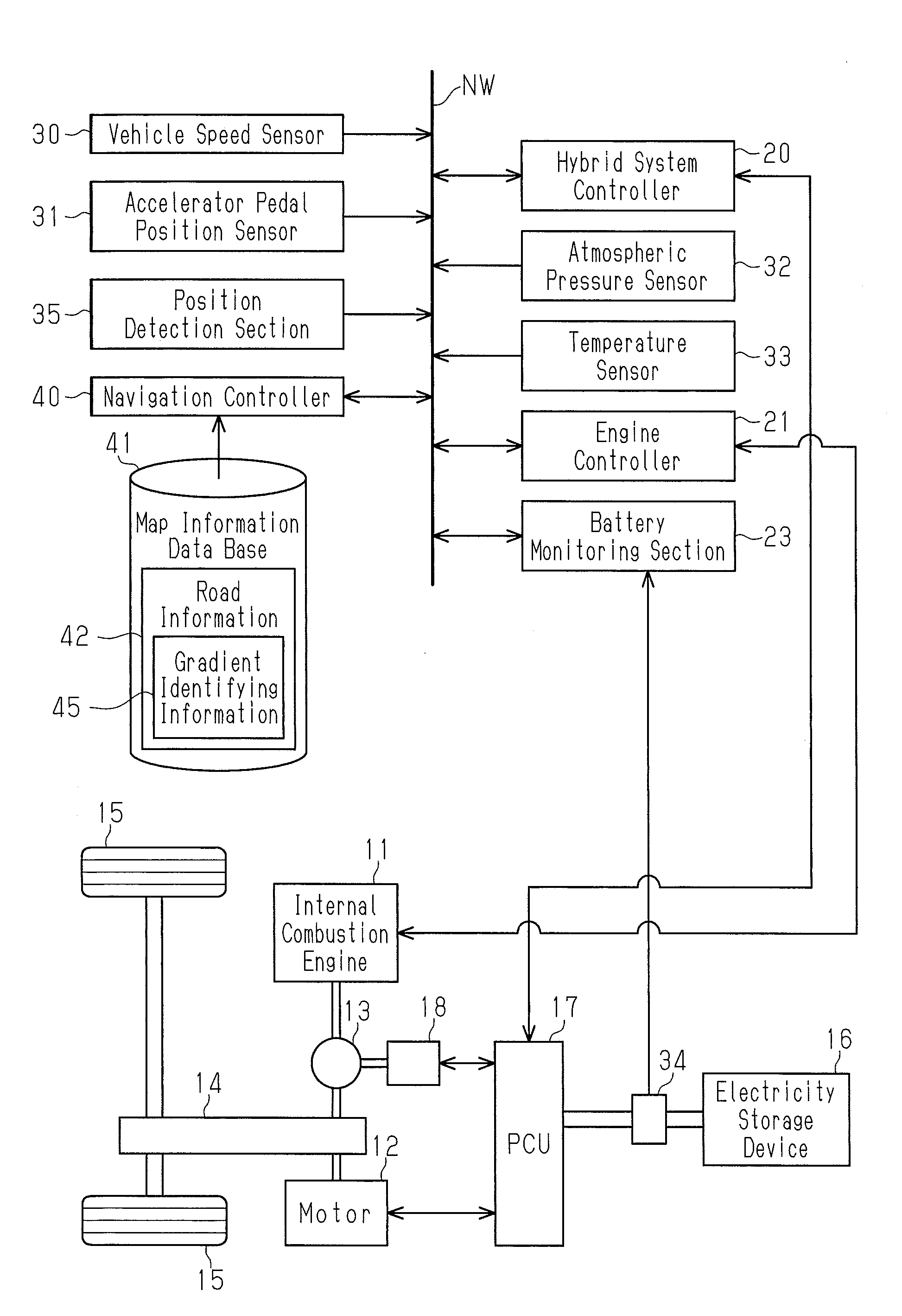
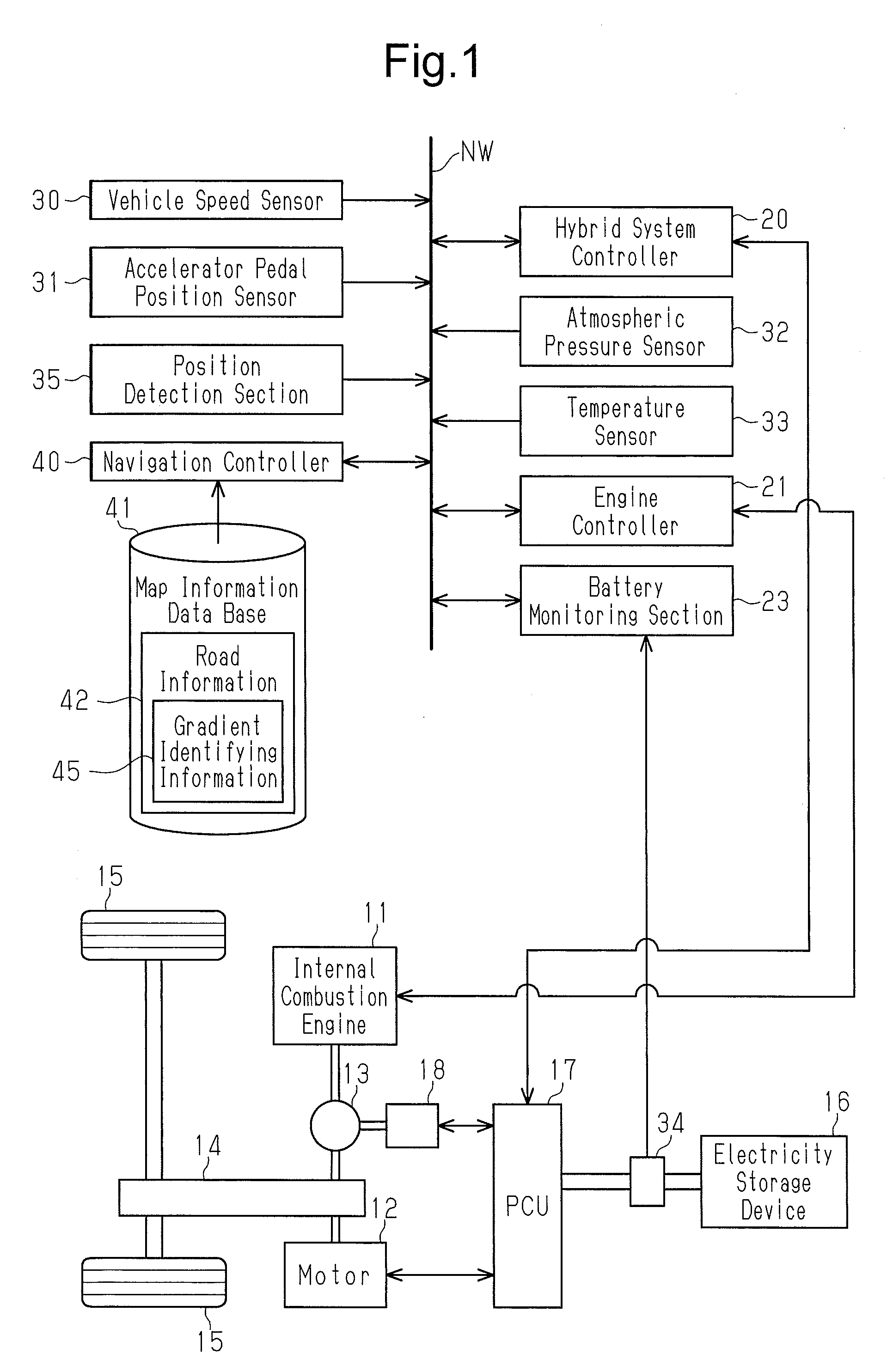
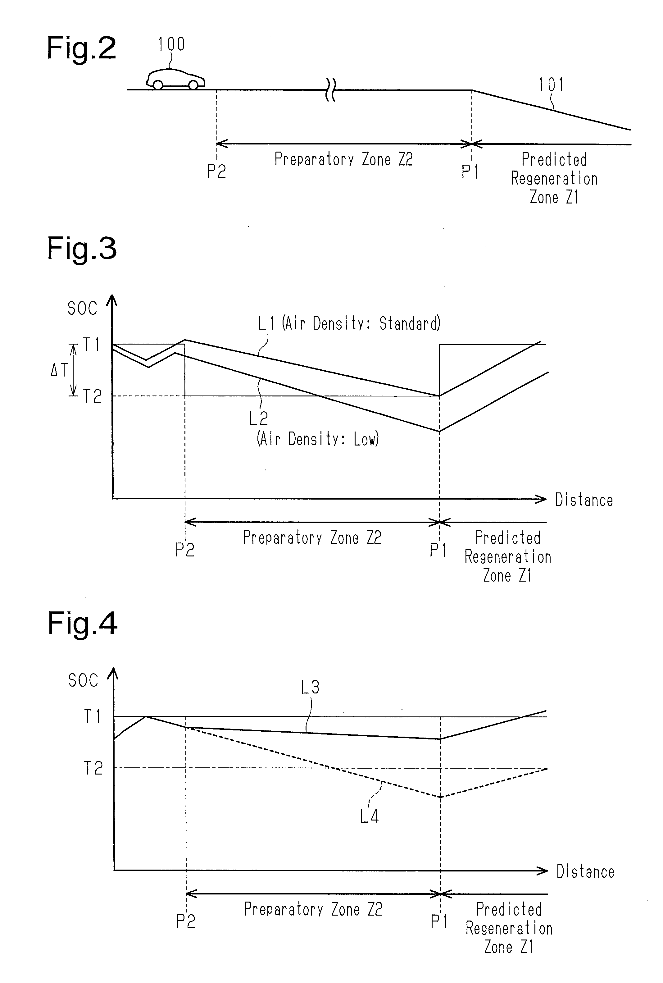
[0027]A vehicle control device according to a first embodiment will now be described. In the present embodiment, description will be given assuming that the vehicle is a hybrid vehicle, which is capable of charging an electricity storage device using the power of the internal combustion engine and regenerative braking.

[0028]As shown in FIG. 1, the vehicle includes an internal combustion engine 11 and a motor 12 as drive sources. The engine 11 is mechanically coupled to drive wheels 15 via a power split mechanism 13 and a speed reducing mechanism 14. The motor 12 receives electricity from an electricity storage device 16, which is a drive source, via a power control unit (PCU) 17, which includes an inverter section circuitry and a converter section circuitry. The electricity storage device 16 is a rechargeable battery. The motor 12 is coupled to the drive wheels 15 via the speed reducing mechanism 14. The motor 12 is capable of performing regenerative braking to generate electricity ...


PUM


Abstract

When an air density is relatively low and a predicted regeneration zone is present within a predetermined travel distance, a vehicle control device executes at least one of the following: i) prohibition of setting a target value of a remaining battery level to a corrected target value; and ii) prohibition of control of an engine and a motor based on the corrected target value.

Description

BACKGROUND OF THE DISCLOSURE[0001]The present disclosure relates to a vehicle control device that controls a vehicle that uses an internal combustion engine and a motor as drive sources.[0002]A hybrid vehicle, which uses an internal combustion engine and a motor as drive sources, performs regenerative braking, in which the motor functions as a generator, for example, during deceleration.[0003]Recently, regarding hybrid vehicles, techniques have been proposed for adjusting the remaining battery level of an electricity storage device in a well-planned manner by using information related to a driving environment. For example, Japanese Laid-Open Patent Publication No. 2012-147554 discloses a vehicle control device that sets a lower a target value of the state of charge (SOC), which indicates the remaining battery level, when it is predicted that regenerative braking will take place in the advancing direction of the vehicle and it is determined that acceleration is unlikely to be perform...

Claims


Application Information

Patent Timeline
Patent Type & Authority Patents(United States)
IPC IPC(8): B60L9/00B60W30/18B60K6/445B60L11/18B60W50/00B60W10/08B60W10/06B60W20/00B60W10/26
CPCB60W20/14B60K6/445B60L11/1862B60W10/06B60W10/08B60W10/26B60W20/12B60W30/18127B60W50/0097B60W2510/244B60W2550/12B60W2550/13B60W2550/143B60W2550/402B60W2710/244Y10S903/93B60W2552/15B60W2555/40B60L7/10B60L2240/622B60L2240/642B60L2240/66B60L2240/662B60L2240/667B60L2260/54B60L50/16B60L50/61B60L58/13B60W2552/20B60W2555/20B60W2556/50Y02T10/62Y02T10/70Y02T10/7072Y02T10/72Y02T90/16
Inventor MORISAKI, KEISUKE
Owner TOYOTA JIDOSHA KK
Why Eureka
Try Eureka