Impact tool

a technology of impact tool and tool body, which is applied in the direction of portable percussive tools, mechanical control devices, instruments, etc., can solve the problems of affecting its durability, and achieve the effects of preventing the biasing member from falling out, ensuring reliability, and ensuring wear resistan

Active Publication Date: 2016-10-11
MAKITA CORP
View PDF21 Cites 9 Cited by
  • Summary
  • Abstract
  • Description
  • Claims
  • Application Information

AI Technical Summary

Benefits of technology

[0005]It is, accordingly, an object of the invention to provide an improved impact tool in which a biasing member is protected from dust.
[0008]According to the invention, the biasing member which biases the operating member to hold it in the selected position is disposed in the housing space of the housing part. With such a construction, the biasing member can be protected from dust without taking troublesome measures such as covering the biasing member by a dust-proofing cover. As a result, durability of the biasing member can be improved.
[0010]According to this embodiment, the sealing member prevents the lubricant from leaking to the outside of the housing space, so that a sliding part of the driving mechanism can be reliably lubricated by the lubricant. In addition, the sealing member prevents dust from entering the housing space, so that the biasing member can be protected from dust. Further, the biasing member is disposed in the housing space and lubricated by the lubricant in the housing space, so that its wear resistance can be enhanced.
[0012]With such a construction, the biasing member is prevented from falling out of the housing part by the fall prevention member, so that the function of the biasing member can be secured.
[0014]According to this embodiment, the crank mechanism converts rotation of the motor into linear motion and can cause the tool bit to perform striking movement via the striking element.

Problems solved by technology

In the above-described known mode switching mechanism, the biasing member is disposed outside of the housing and therefore affected by dust generated during hammering operation, which impairs its durability.

Method used


Image

  • Impact tool
  • Impact tool
  • Impact tool

Examples


first embodiment

of the Invention

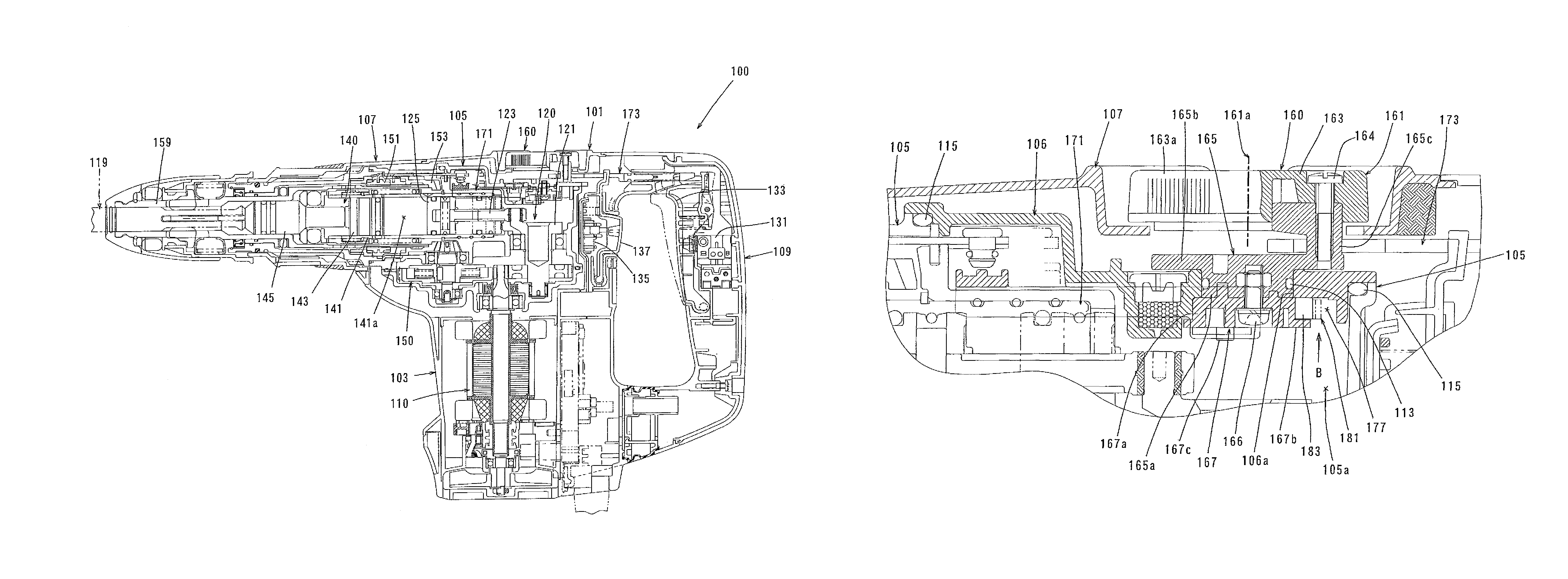
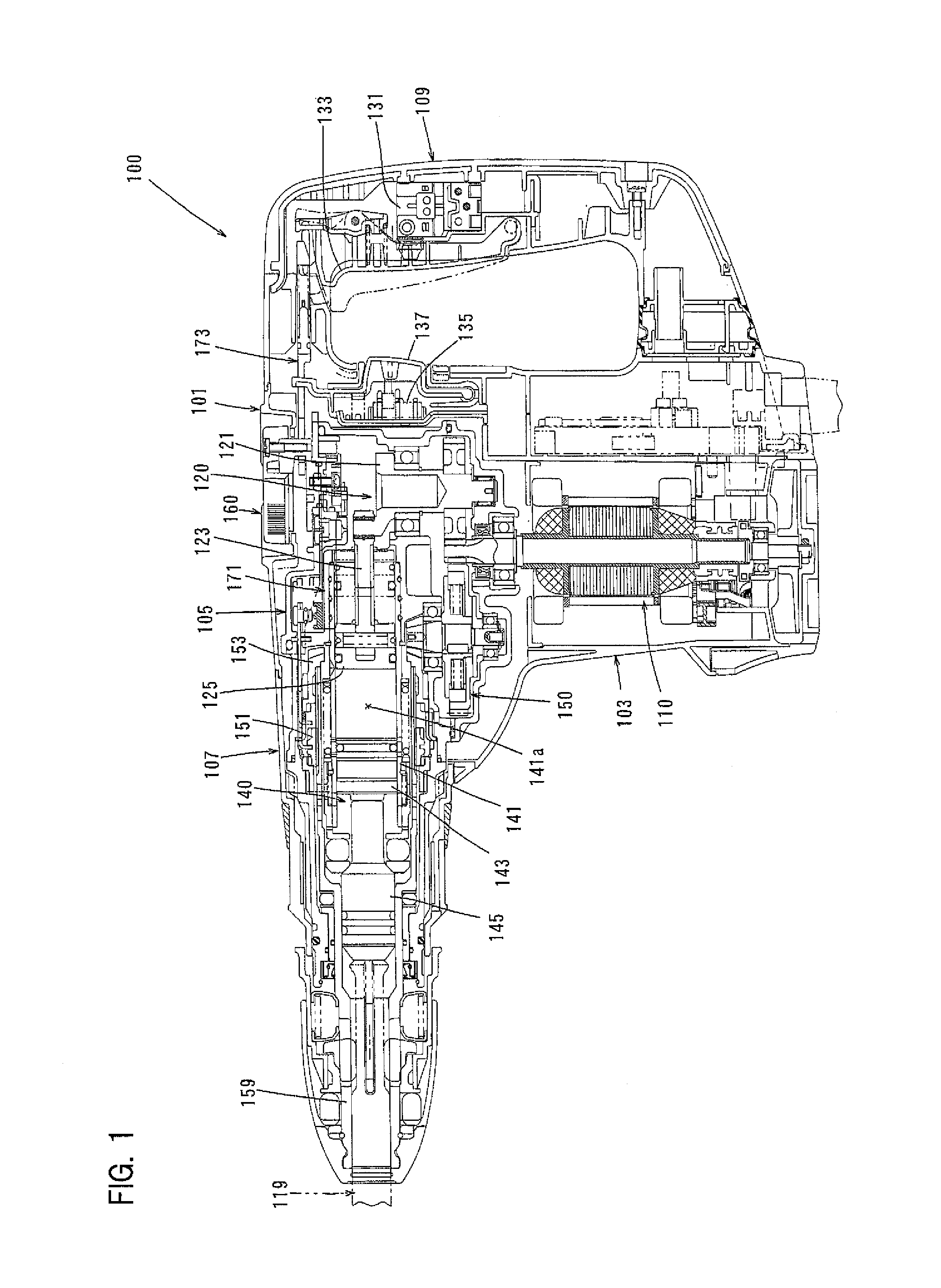
[0025]A first embodiment of the invention is now described with reference to FIGS. 1 to 5. In this embodiment, an electric hammer drill 100 is described as a representative example of an impact tool. As shown in FIG. 1, the electric hammer drill 100 is designed as an impact tool to which a hammer bit 119 is coupled and performs drilling, chipping or other similar operation on a workpiece by causing the hammer bit 119 to linearly move in its axial direction and rotate around its axis. The hammer bit 119 is a feature that corresponds to the “tool bit” according to the invention.

[0026]The hammer drill 100 mainly includes the “tool body” in the form of a body 101 that forms an outer shell of the hammer drill 100. The hammer bit 119 is detachably coupled to a front end region of the body 101 via a cylindrical tool holder 159. The hammer bit 119 is inserted into a bit insertion hole of the tool holder 159 and held such that it is allowed to move in its axial direction with...

second embodiment

of the Invention

[0059]A second embodiment of the invention is now described with reference to FIGS. 6 and 7. This embodiment is a modification to a holding means for holding the switching dial 161 in a selected position. In the other points, this embodiment has the same construction as the above-described first embodiment. Therefore, components or elements which are substantially identical to those in the first embodiment are given like numerals and are not described or only briefly described.

[0060]In this embodiment, a cylindrical roller 183 is disposed as an intervening member between a leaf spring 181 and the lower flanged cylinder 167 of the switching dial 161. The leaf spring 181 and the roller 183 are features that correspond to the “biasing member” and the “intervening member”, respectively, according to the invention.

[0061]As shown in FIG. 7, the leaf spring 181 has a generally arcuate shape protruding rearward, having a convexly forward curved central portion and ring-shape...


PUM


Abstract

It is an object of the invention to provide an improved impact tool in which a biasing member is not affected by dust.An impact tool according to the invention has a driving mechanism 120 for driving a tool bit 119, housing parts 105, 106 that form a housing space 105a in which at least part of the driving mechanism 120 is disposed, and a switching member 160 for switching a drive mode of the impact tool. The switching member 160 has an operating member 161 that is operated by a user for mode switching, and a biasing member 175 that is disposed between the operating member 161 and the housing part 106 and biases the operating member 161 so as to hold the operating member 161 in a selected position. The biasing member 175 is disposed in the housing space 105a.

Description

FIELD OF THE INVENTION[0001]The invention relates to an impact tool which performs a predetermined operation on a workpiece by at least linear movement of a tool bit in its axial direction.[0002]Cross reference is made to the Japanese patent application JP2012-253722 filed on Nov. 19, 2012 the entire contents of which are herein incorporated by reference.BACKGROUND OF THE INVENTION[0003]Japanese non-examined laid-open Patent Publication No. 2002-292579 discloses a mode switching mechanism for switching an operation mode of a tool bit in an impact tool. This mode switching mechanism has an operating member which is turned by a user to switch the operation mode. When the operating member is turned to select a predetermined operation mode, the operating member is positioned and held in that angular position by a biasing member. The biasing member is formed by a leaf spring fastened to a housing and holds the operating member in the selected angular position by elastically engaging with...

Claims


Application Information

Patent Timeline
Patent Type & Authority Patents(United States)
IPC IPC(8): B25D16/00B25F5/00B25D17/26H01H9/06G05G5/06
CPCB25D16/006B25D17/26B25F5/001B25D2216/0023B25D2217/0096B25D2250/255B25D2250/345B25D2250/365B25D2250/381G05G5/06H01H9/06
Inventor TAKEUCHI, HAJIMEFURUSAWA, MASANORITADA, YOSHIRO
Owner MAKITA CORP
Why Eureka
Try Eureka