
Device and method for working material

a technology for working materials and devices, applied in applications, ultrasonic/sonic/infrasonic image/data processing, ultrasonic/sonic/infrasonic diagnostics, etc., can solve the problems of increased risk of infection, postoperative healing of wounds, and extended time, and achieve the effect of reducing the interaction depth of the tool in the plaster

Active Publication Date: 2016-10-11
DEPUY (IRELAND) LTD
View PDF13 Cites 2 Cited by
  • Summary
  • Abstract
  • Description
  • Claims
  • Application Information

AI Technical Summary

Benefits of technology

The patent describes a system where a tool can work on a material without needing to have all the necessary properties of the material captured first. This is done by using data from a database that describes the material. The system can also use data captured directly from the tool when it is working on the material to make sure the tool is following the correct path. This improves safety during automatic path-finding. One possible application is cutting up casts to protect the patient's skin from injury. The system can detect when the tool comes close to the patient's skin and push out the support at the head of the tool to decrease the interaction depth and protect the patient.

Problems solved by technology

Thus it is the paramount goal to protect the very closely abutting hard meninges, the dura mater, to prevent any type of injury by the tool that is used, as injuries of the dura mater can lead to an extended time for the surgery and also the postoperative healing of the wound, as well as to an increased risk of infection.
Beyond that, in the event of an injury of the dura mater, further complications (healing of the wound, mortality and increased treatment costs must be considered.
This functional mechanism is known to fail, for example typically in the event of local variations of thickness of the cranial bone, as well as in the case of an adhesion of the dura mater to the cranial bone.
Then, tearing of the dura mater can occur in a section that is not visible, as a result of which a direct reaction to this type of damage to the dura mater is not possible, and the damage thus often continues up to the end of the cutting process.
During a surgical procedure, such an injury is to be repaired in a targeted manner, for which often the required sutures or duraplastic in addition to a significant extension of the surgical procedure can also be associated with the danger of a liquid fistula and thus the risk of a postoperative infection with a significant increase of mortality, as well as increased costs.
The cutting technique described above thereby leads to a residual osseous gap, which is the result of a cutting defect because of the bore holes as well as the cutting kerf.
In other medical areas such as, for example, in the mouth, jaw or facial surgery, as well as spinal column surgery, comparable problems result with respect to the protection of the soft tissue.
In this type of working of a material it is considered to be disadvantageous, however, when the performance of the tool that is used varies, because of this known method or the known apparatus, it being especially known in the case of cutting or cutting tools that a decrease in performance can under certain circumstances even lead all the way to stopping n a material that is to be worked on, i.e. arresting of the tool in the material.
Especially in medical applications, as well as in general in any type of application of working on material, this represents a significant disadvantage, as, at the moment it stops, a tool of this type can get out of control.
At best, such a previously known apparatus for working on material can only be used with sufficient safety in this type of processing, if it is based on a rotating operating principle such as, for example, drilling or cutting, not, however, by working by sawing.

Method used


Image

  • Device and method for working material
  • Device and method for working material
  • Device and method for working material

Examples


Embodiment Construction

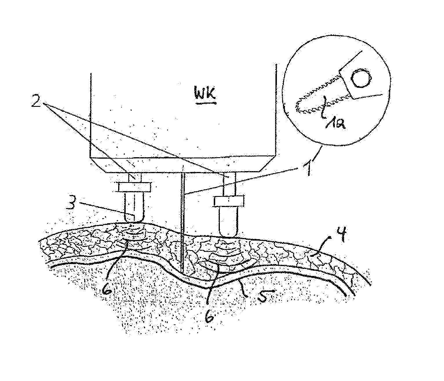
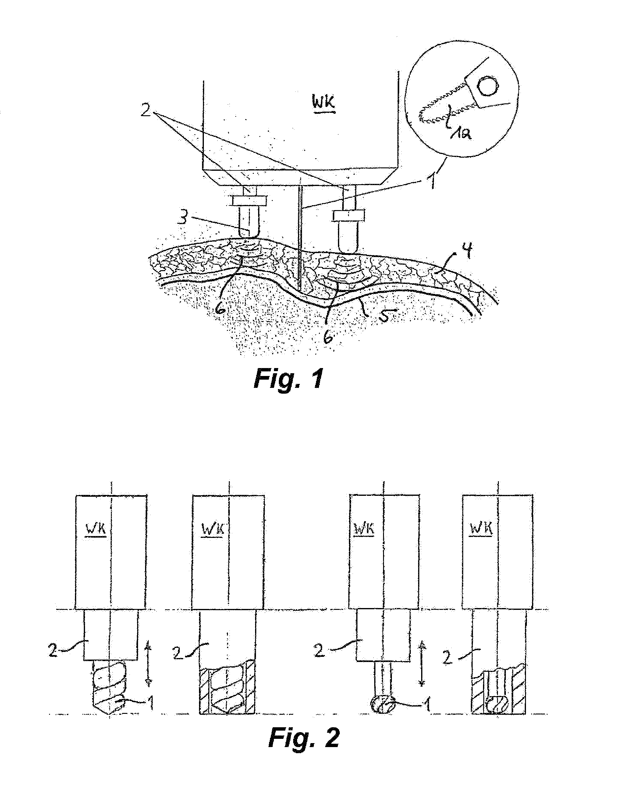
[0057]In a lateral cross section, FIG. 1 shows a tool head WK in accordance with the invention on which is mounted a tool 1 that here is designed as per the explanatory additional illustration as a saw blade 1a in order to thus saw cut into a cranial bone 4 freed of skin on the outside, with a kerf width that corresponds to the thickness of the saw blade.

[0058]In order to prevent splitting open the cranial bone during the cutting process, such that dura mater 5 underneath the cranial bone 4 is injured, here according to the invention the tool head carries two supports 2 that flank the saw blade 1 and thus surround the tool 1. The supports 2 are adjustable by unillustrated actuators within the tool head WK and are pushed out of the tool head by these actuators or can be pulled back into the tool head, so that the position of the lower end of each of the supports 2 can be changed.

[0059]According to one embodiment, this can be done in that the position of the tool 1 is captured by an e...


PUM

PropertyMeasurementUnit
angleaaaaaaaaaa
heightaaaaaaaaaa
ultrasound impulsesaaaaaaaaaa

Abstract

The invention relates to a device for working material, in particular for working tissue or bone, comprising a tool head and a tool arranged thereon, wherein the tool head (WK) has at least one support element (2) which is adjustable relative thereto and by means of which the tool head (WK) can be supported on the surface of a material (4) that is to be worked, wherein the position of the tool (1) relative to a material surface to be worked is adjustable through controlled or regulated adjustment of the at least one support element (2) by means of an actuator, depending on data that can be fed to a controlling / regulating unit of the at least one actuator during working of the material.

Description

CROSS REFERENCE TO RELATED APPLICATIONS[0001]This application is the US-national stage of PCT application PCT / EP2008 / 008699, filed 15 Oct. 2008, published 23 Apr. 2009 as WO2009 / 049863, and claiming the priority of German patent application 102007050017.5 itself filed 17 Oct. 2007.FIELD OF THE INVENTION[0002]The invention relates to an apparatus for working material and comprising a head carrying a tool. The invention further relates to a method of working on material where the tool head with the tool mounted on it is guided along the surface of the material that is to be worked.BACKGROUND OF THE INVENTION[0003]The described apparatus and method are generally suitable for working on any type of material, here especially tissue or bone, and thus are also usable in medical technology.[0004]When working on materials, especially in medicine and here especially for working on tissue and bone, it is important to have information available about the local properties of the material that is...

Claims


Application Information

Patent Timeline
Patent Type & Authority Patents(United States)
IPC IPC(8): A61B17/00A61B17/16A61B8/08
CPCA61B17/1695A61B8/0808Y10T83/04Y10T83/141
Inventor RADERMACHER, KLAUSFOLLMANN, AXELHEGER, STEFAN
Owner DEPUY (IRELAND) LTD
Learn More