
Body-building power generation apparatus and a method of generating power using the same

a power generation apparatus and body-building technology, applied in the direction of electric generator control, gymnastic exercise, machines/engines, etc., can solve the problems of inability to solve the inability to achieve the discontinuity of human strength on power generation, etc., to achieve the effect of improving efficiency, reducing costs, and increasing propagation

Active Publication Date: 2016-10-04
YIN WUJI
View PDF9 Cites 1 Cited by
  • Summary
  • Abstract
  • Description
  • Claims
  • Application Information

AI Technical Summary

Benefits of technology

The present invention is a device that can generate electricity from body-building exercises. This device can provide energy to homes, offices, or leisure facilities, and also act as a backup power source in case of power failures or piezoelectricity.

Problems solved by technology

1. The time people spend on fitness maintaining and body building is not taken into account in the prior art. Generally, a person would spend over ten minutes, but less than two hours on fitness exercises. The time that the power generation apparatus is directly driven by the fitness exercises is very limited, thus, the generator can only work for a very limited time period, which means, electricity can be produced only when the fitness exercise is under operation.
2. Technically, the influence of factors such as the explosive force, attenuating property, instability, and the discontinuity of human strength on power generation has not been resolved.
3. The power generated by body-building exercises is not only small in amount, but also questionable in quality. In most cases, the voltage produced cannot effectively charge the rechargeable battery. Even when the battery is charged to a certain extent, it still cannot satisfy the operating requirements of household appliances or office machinery which are sensitive to voltage and current fluctuation.

Method used


Image

  • Body-building power generation apparatus and a method of generating power using the same
  • Body-building power generation apparatus and a method of generating power using the same
  • Body-building power generation apparatus and a method of generating power using the same

Examples


example 1

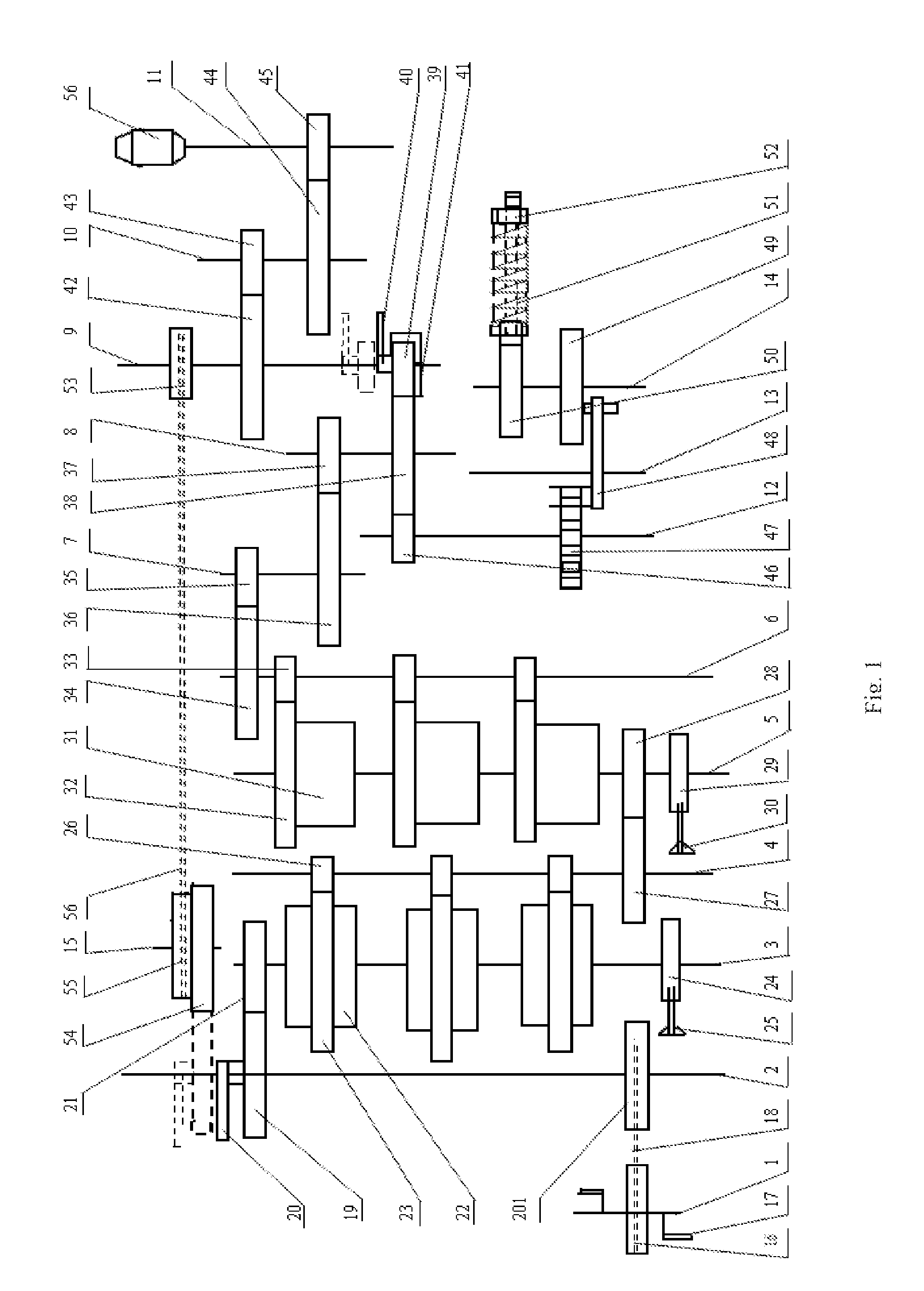
[0065]FIG. 1 schematically shows a foot pedal type energy storage power generation apparatus comprising six energy storage boxes of two stages and a hand operating clutch switching mechanism. The fitness device is a foot-pedal type device. The energy storage mechanism comprises two stages of energy storage boxes, with each stage comprising three energy storage boxes of the same specifications. A non-return ratchet is arranged on the center axle of each stage energy storage box, in order to ensure that the energy can be transmitted only from high level potential energy in the first stage energy storage boxes to low level potential energy in the second stage energy storage boxes. The energy storage boxes in the two stages are in series connection with one another, and store energy like an impounding reservoir retains water. The coil spring damper speed regulator module with adjustable tensile force acts as a valve controlling the outflow volume of potential energy. Two hand operating ...

example 2

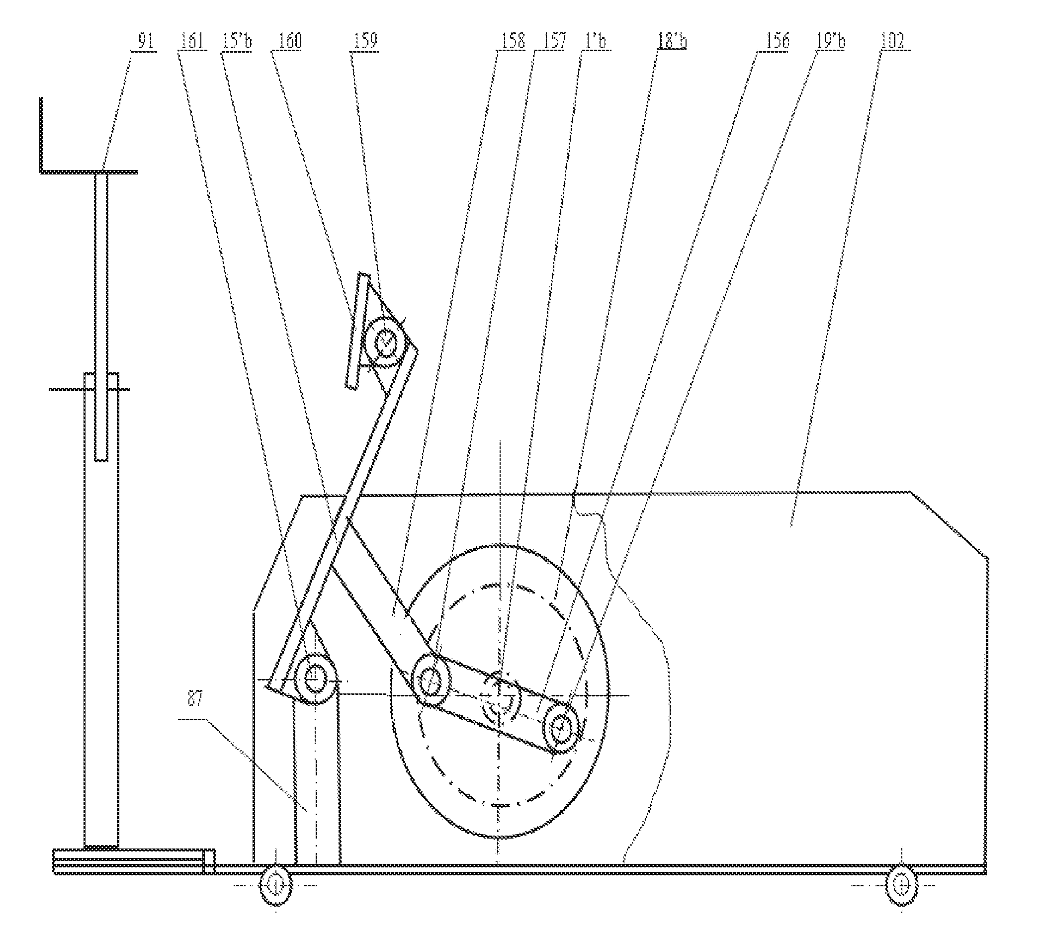
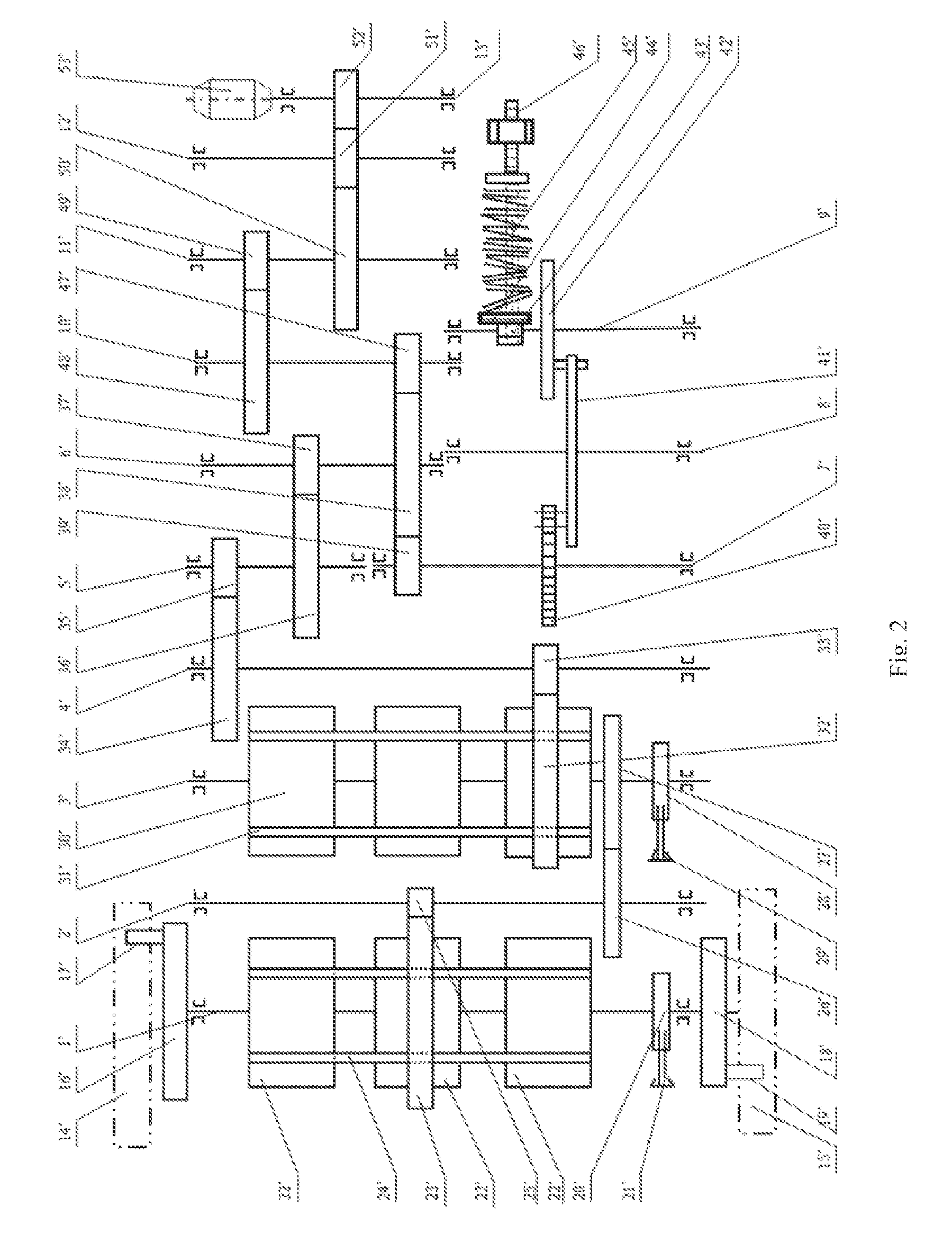
[0067]FIG. 2 schematically shows an energy storage power generation apparatus comprising two combined-type energy storage gears of two stages and a foot-pedal type movement mechanism or a hand operating lever push / pull movement mechanism. The motion part of the fitness device comprises two discs having eccentric shafts which are fixed on an axle 1′, a fixed support, and a foot pedal piece or hand operating push / pull piece. The foot pedal type fitness movement mechanism is as shown in FIG. 4 and FIG. 5 and the hand operating lever push / pull movement mechanism is as shown in FIG. 6, wherein the fitness devices are of bilaterally symmetrical arrangement. The energy storage mechanism adopts combined-type energy storage gears of two stages, with non-return ratchet arranged on the center shaft of each stage energy storage gear, so that the two stages of energy storage gears are like two reservoirs in series connection, and the energy can only flow from the high level potential energy posi...

example 3

[0069]FIG. 3 schematically shows an energy storage power generation apparatus comprising six energy storage boxes of three stages and a movement mechanism using removable push / pull rod or hand operating turntable. The movement mechanism is in form of a hand operating disc and a detachable hand push / pull rod fixed to the two ends of a shaft. A shaft sleeve is arranged on one end of a push / pull rod 18″. A disc 16″ which is fixed to an axle 1″ has an eccentric shaft 17″, wherein the eccentric shaft 17″ is connected to the shaft sleeve at one end of the push / pull rod 18″, and the push / pull rod 18 can be detached or mounted at anytime. The apparatus adopts three-stage combined-type energy storage mechanism. The power gear directly drives the gear of the energy storage box. A non-return ratchet is arranged on the drive shaft of each stage energy storage box, so that the three stages of energy storage boxes are like reservoirs in series connection, and the energy can only flow from the hig...


PUM


Abstract

The present disclosure relates to a body-building power generation apparatus and a method of generating power using the power generation apparatus, comprising at least one fitness device, an energy storage device connected with the fitness device for transforming and storing the kinetic energy transmitted from the fitness device, wherein the energy stored in the energy storage device can be transformed into kinetic energy and outputted by an output mechanism connected with the energy storage device, a speed changing mechanism, receiving the kinetic energy from the output mechanism and outputting said kinetic energy after adjusting it, and a generator connected to the speed changing mechanism for transforming the adjusted kinetic energy into electric energy. The body-building power generation apparatus according to the present disclosure can satisfy or at least partially supplement the need of electricity in residential areas, office buildings, or leisure facilities; it can also act as backup power source to alleviate piezoelectricity or power failure in rush hours.

Description

[0001]This application is the U.S. national stage of international patent application PCT / CN2013 / 079248, filed Jul. 11, 2013, which claims priority to Chinese Patent Application No. 201310089944.6, filed Mar 20, 2013; Chinese Patent Application No. 201310091973.6, filed Mar. 21, 2013; and Chinese Patent Application No. 201320199991.1, filed Apr. 19, 2013, each of which is hereby incorporated by reference in its entirety.TECHNICAL FIELD[0002]The present disclosure relates to the technical field of body-building power generation, in particular to a body-building power generation apparatus and a method of generating power using said power generation apparatus.TECHNICAL BACKGROUND[0003]As more and more countries are striving for conserving energy and developing green energy, generating power through body-building exercises, due to its characteristic of environmental friendliness, has been widely researched and developed by many institutions and individuals at home and abroad. For exampl...

Claims


Application Information

Patent Timeline
Patent Type & Authority Patents(United States)
IPC IPC(8): A63B24/00F03G5/00F03G5/06H02P9/06H02J7/32H02K7/18
CPCA63B21/0055A63B21/0054F03G5/00F03G5/06H02P9/06H02J7/32H02K7/1861A63B22/0056A63B2208/0233A63B21/023F03G5/065F03G5/103F03G5/064F03G5/095
Inventor YIN, XIAOLINYIN, WUJI
Owner YIN WUJI
Learn More