Electronic component manufacturing method and electrode structure

a manufacturing method and electrode technology, applied in the direction of vacuum evaporation coating, coating, electric discharge tubes, etc., can solve the problems of narrow trench opening, narrow trench opening, and need for thick deposited ti and tin laminated barrier film, so as to reduce the opening diameter and improve the yield of gate-last devices , the effect of reducing the diameter of the opening

Active Publication Date: 2016-09-06
CANON ANELVA CORP
View PDF31 Cites 0 Cited by
  • Summary
  • Abstract
  • Description
  • Claims
  • Application Information

AI Technical Summary

Benefits of technology

[0015]Meanwhile, in the method described in Patent Document 3, a first barrier layer and a second barrier layer need to be formed so that agglomeration of a low-melting-point metal deposited at high temperature can be prevented or reduced and a recess can be filled with the low-melting-point metal with high throwing power. This leads to a problem that the barrier layers are increased in thickness. Meanwhile, the method described in Patent Document 4 enables embedding of Al without reducing the opening diameter even in a minute trench having an opening diameter of 22 mm or less. However, in the method described in Patent Document 4, the Al layer needs to be embedded under a temperature condition that allows the layer to flow. In the case of a minute trench having an opening diameter of 15 nm or less, there is a concern that unevenness on the surface of the Al film may affect the performance of electronic components.
[0016]The present invention was made in consideration of the foregoing conventional problems. It is an object of the present invention to provide an electronic component manufacturing method, capable of solving the problems described above, suppressing reduction in a trench opening, and suppressing diffusion of a metal film embedded in a trench.
[0019]According to the present invention, metal can be embedded even in a minute trench having an opening diameter of 15 nm or less while suppressing reduction in opening diameter by forming a first electrode constituting layer (e.g., a TiAl film) formed on a workplace (first step) with a recess (e.g., a trench) formed therein, forming an ultrathin barrier layer (e.g., a TiAlN film) by forming a nitride layer by plasma-nitriding a surface of the first electrode constituting layer (e.g., the TiAl film) (second step), and forming a second electrode constituting layer (e.g., on Al wiring layer) on the ultrathin barrier layer (e.g., the TiAlN film) (third step). Therefore, even when the electronic component manufacturing method including the step of embedding a metal film according to the present invention is applied to a method for manufacturing a wiring, a metal film can be embedded while suppressing reduction in an opening diameter of a minute trench having an opening diameter of 15 nm or less. Moreover, in an electrode structure formed by the electronic component manufacturing method according to the present invention, a metal wiring layer is formed flat without unevenness on an ultrathin barrier layer (e.g., a TiAlN film) while suppressing reduction in an opening diameter of a minute trench having an opening diameter of 15 nm or less. Thus, an effect is achieved that embedding performance can be enhanced and the yield of a gate-last device can be improved.

Problems solved by technology

However, the above techniques have the following problems, respectively.
The method involving sputtering at a high pressure of 1 Torr or more described in Patent Document 1 has a problem that, even though deposition on the sidewall of the trench can be performed, the trench opening is narrowed when the trench opening is reduced to 15 nm or less.
Moreover, the Al embedding method described in Patent Document 2 has a problem that the Ti and TiN laminated barrier film needs to be thickly deposited to suppress Al diffusion.
There is also a problem that, since the Seed-Al layer is further formed on the Ti and TiN laminated barrier film to facilitate Al migration, the trench opening is narrowed.
This leads to a problem that the barrier layers are increased in thickness.
In the case of a minute trench having an opening diameter of 15 nm or less, there is a concern that unevenness on the surface of the Al film may affect the performance of electronic components.

Method used


Image

  • Electronic component manufacturing method and electrode structure
  • Electronic component manufacturing method and electrode structure
  • Electronic component manufacturing method and electrode structure

Examples


embodiment

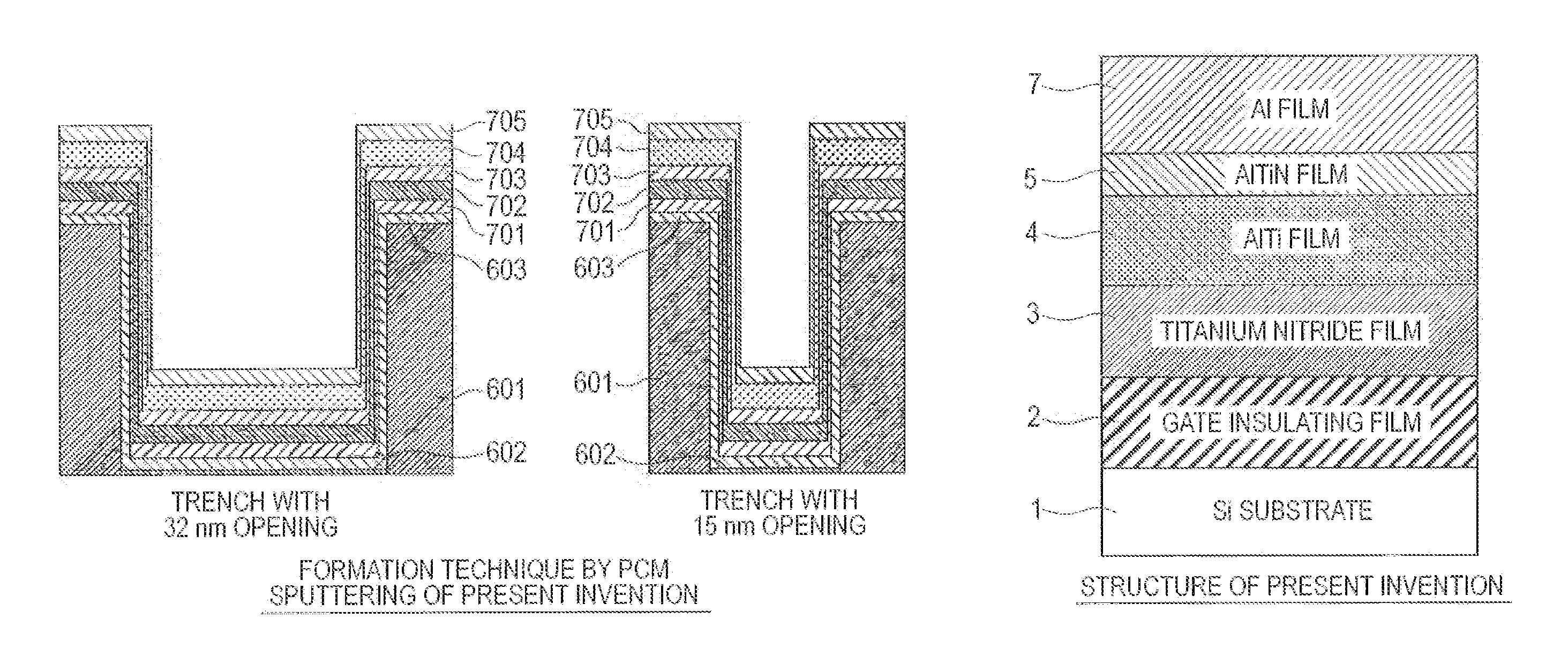
[0049]As a result of intensive studies to solve the above problem, the present inventors have completed the present invention by finding out that a second electrode constituting layer (e.g., an Al wiring layer) can be directly embedded smoothly without unevenness on an ultrathin barrier layer (e.g., a TiAlN film) even when there is no Seed-Al layer further formed between the ultrathin barrier layer (e.g., the TiAlN film) and the second electrode constituting layer (e.g., the Al wiring layer) by forming a first electrode constituting layer (e.g., a TiAl film) in a recess (e.g., a trench) formed in a workpiece (a first step), forming the ultrathin barrier layer (e.g., the TiAlN film) by plasma nitriding the surface of the first electrode constituting layer (e.g., the TiAl film) to form a nitrided layer (a second step), and then forming the second electrode constituting layer (e.g., the Al wiring layer) on the ultrathin barrier layer (e.g., the TiAlN film) (a third step). More specific...

first example

[0090]A first example of the present invention is described in detail with reference to the drawings. FIGS. 15D and 15E are diagrams showing a first step of forming a TiAl film in a trench structure using the PCM sputtering apparatus 100 of the present invention shown in FIGS. 1 and 6, a second step of forming a TiAlN layer on a TiAl surface layer by plasma nitridation, and then a third step of Al embedding. First, as shown in FIG. 15D, a TiAl film 905 is deposited in trench structures 901 and 902 by sputtering. A metal alloy target of TiAl is used as a target, and Ar is used as sputtering gas. Next, the TiAl film 905 is plasma-nitrided using a Ti metal target and nitrogen gas as a gas to form a nitrogen plasma, thus converting the TiAl film 905 into a TiAlN film 905. Note that although the whole TiAl film 905 is converted into the TiAlN film 905 by plasma nitridation in this example, only a part (e.g., a surface) of the TiAl film 905 may be converted. Next, as shown in FIG. 15E, an...

second example

[0093]A second example is one applied to the gate-last method.

[0094]The second example of the present invention is described below with reference to the drawings. FIGS. 15A to 15F are diagrams showing steps of a method for manufacturing a semiconductor device as the second example of the present invention. In this example, in a region to form an N-type MOSFFT as a first region and a region to form a P-type MOSFET as a second region, metal gate electrodes that realize suitable effective work functions are formed by performing the first step of depositing a TiAl film, the second step of forming a TiAlN barrier layer by plasma nitridation and the third step of Al embedding in the first example.

[0095]As shown in FIG. 15A, trench structures 901 and 902 are formed in the region to form the N-type MOSFFT and the region to form the P-type MOSFFT. Next, as shown in FIG. 15B, a metal nitride film B903 and a metal nitride film C904 are formed using the sputtering apparatus of the present inven...


PUM

PropertyMeasurementUnit
opening diameteraaaaaaaaaa
temperatureaaaaaaaaaa
thicknessaaaaaaaaaa

Abstract

It is an object of the present invention to provide an electronic component manufacturing method, capable of suppressing reduction in a trench opening and suppressing diffusion of a metal film embedded in a trench. An embodiment of the present invention is an electronic component manufacturing method, including the steps of: forming a first electrode constituting layer (e.g., a TiAl film) in a recess (e.g., a trench) formed in a workpiece; forming an ultrathin barrier layer (e.g., a TiAlN film) by forming a nitride layer by plasma-nitriding a surface of the first electrode constituting layer; and forming a second electrode constituting layer (e.g., an Al wiring layer) on the ultrathin barrier layer.

Description

CROSS-REFERENCES TO RELATED APPLICATIONS[0001]This application is a continuation application of International Application No. PCT / JP2012 / 006104, filed Sep. 25, 2012, which claims the benefit of Japanese Patent Application No. 2012-012240, filed Jan. 24, 2012. The contents of the aforementioned applications are incorporated herein by reference in their entireties.TECHNICAL FIELD[0002]The present invention relates to an electronic component manufacturing method and an electrode structure, and more particularly relates to an electronic component manufacturing method and an electrode structure, the method including a step of embedding a metal film in a recess formed in a workpiece.BACKGROUND ART[0003]For conventional semiconductor integrated circuits, a gate-first method has been used in which a gate insulating film and a gate electrode are formed first on a wafer surface, and then processing by etching is performed. In recent years, thinning of a gate insulating film in a MOSFET has be...

Claims


Application Information

Patent Timeline
Patent Type & Authority Patents(United States)
IPC IPC(8): H01L29/41H01L21/28H01L21/321H01J37/34C23C14/58H01L21/3205H01L29/49C23C14/35H01L21/8238C23C14/04C23C14/34H01L21/285H01L29/66H01L21/768
CPCH01L29/4966C23C14/046C23C14/345C23C14/35C23C14/586C23C14/5826H01J37/3402H01J37/3447H01J37/3452H01L21/28088H01L21/321H01L21/32051H01L21/823842H01L21/2855H01L21/76843H01L21/76856H01L29/66545
Inventor MATSUO, AKIRASHIBUYA, YOHSUKEKITANO, NAOMUMORIMOTO, EITAROHYAMAZAKI, KOJISATO, YUSEINO, TAKUYA
Owner CANON ANELVA CORP
Why Eureka
Try Eureka